Checking the assemblies 2 - 7
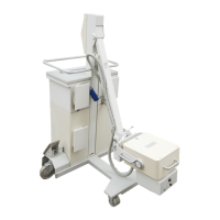
Siemens AG SPR8-125.061.02 Page 7 of 8 POLYMOBIL Plus
Medical Engineering Rev. 01 01.00 TD SD 24
D950 capacitor charging circuit 2
LED:
Fuse:
Test points:
D970 Capacitor bank 2
LED:
Fuse:
Test points:
LINE (V25) Line voltage ok
450 Vcc (V30) Capacitor voltage present (the voltage can also be considerably lower
than 450 V)
F1 10 AT Charging circuit
ERR Error output charging error
VC Capacitor voltage 1 V 100 V
IC Capacitor charging current
FR1 Charging circuit frequency (dependent on the line voltage and VC)
GND Ground
CAR Signal to enable the charger
FR2 Frequency of the auxiliary power supply
OK Signal to indicate the full charge
V1 - V10 Capacitor voltage present at C1 - C10
F1 - F10 20AF Capacitor charging voltage for C1 - C10
F11 80AF Capacitor voltage for inverter
F12 20AF Charging voltage for capacitor bank
-VCC, +VCC Capacitor voltage