POLYMOBIL Plus SPR8-125.061.02 Page 2 of 8 Siemens AG
Rev. 01 01.00 TD SD 24 Medical Engineering
6 - 2 Replacing important components
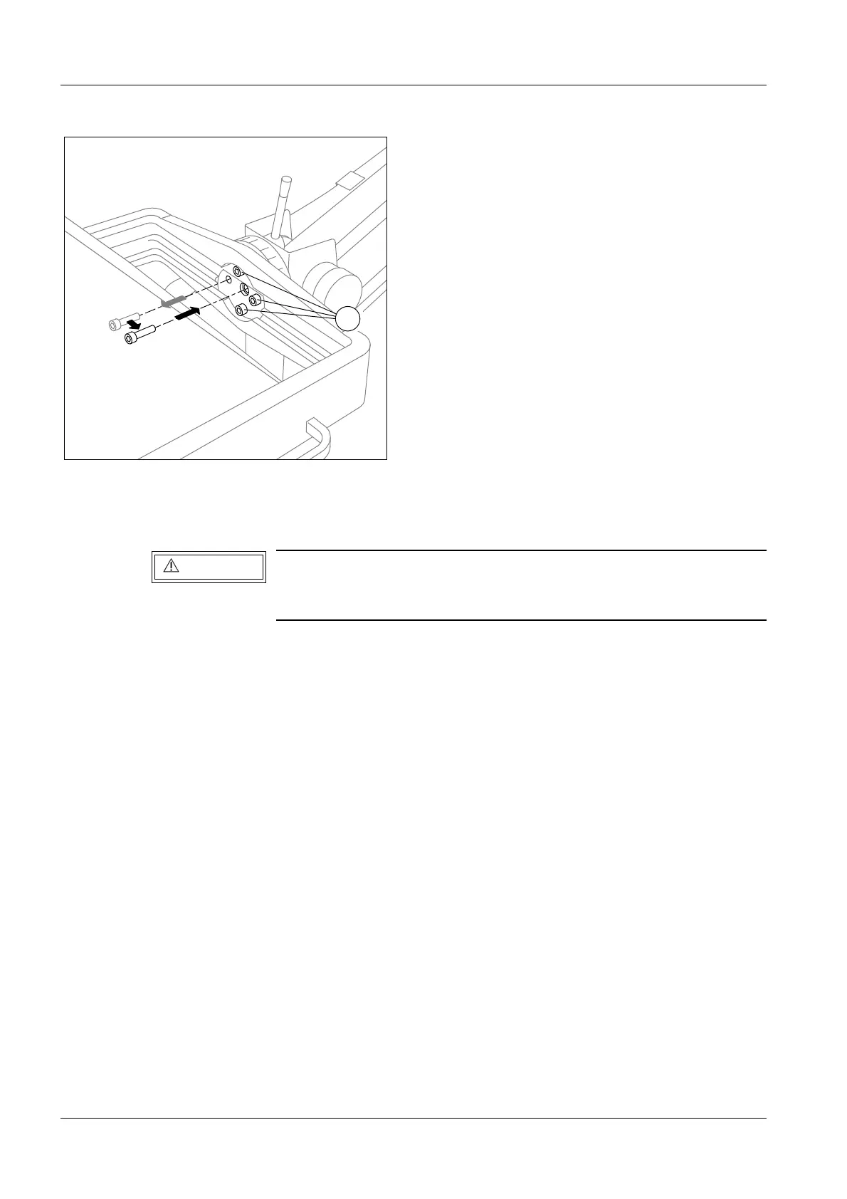
• Take out one of the four mounting screws and insert it into the threaded hole and tighten
it (arrow/Fig.3).
• Place a pad under the single tank generator.
• Disconnect the single tank generator together with the bracket from the stand by
removing the three remaining screws (4/Fig.3).
• Lower the single tank generator to the pad.
• The single tank generator is installed in reverse sequence.
- Secure the three mounting screws (4/Fig.3) with Loctite 242 and tighten them.
- Remove the fourth mounting screw from the threaded hole (arrow/Fig.3) and reinstall it
in its former position. Secure the screw with Loctite 242.
- Test the torque of the mounting screws ;
Nom: 25 Nm, Tolerance
± 10%.
• Reinstall the collimator in reverse sequence.
• Set the tube current (refer to "Setting the tube current for the exposure", pp 5-12).
• Check the coincidence of the light and radiation fields and adjust, if necessary
(refer to "Coincidence of light and radiation fields", pp 5-15)
This is a safety device to prevent the arm of the unit from flying
upward if the lever for the transport lock is inadvertantly
activated.
4
Fig. 3
WARNING