Replacing important components 6 - 7
Siemens AG SPR8-125.061.02 Page 7 of 8 POLYMOBIL Plus
Medical Engineering Rev. 01 01.00 TD SD 24
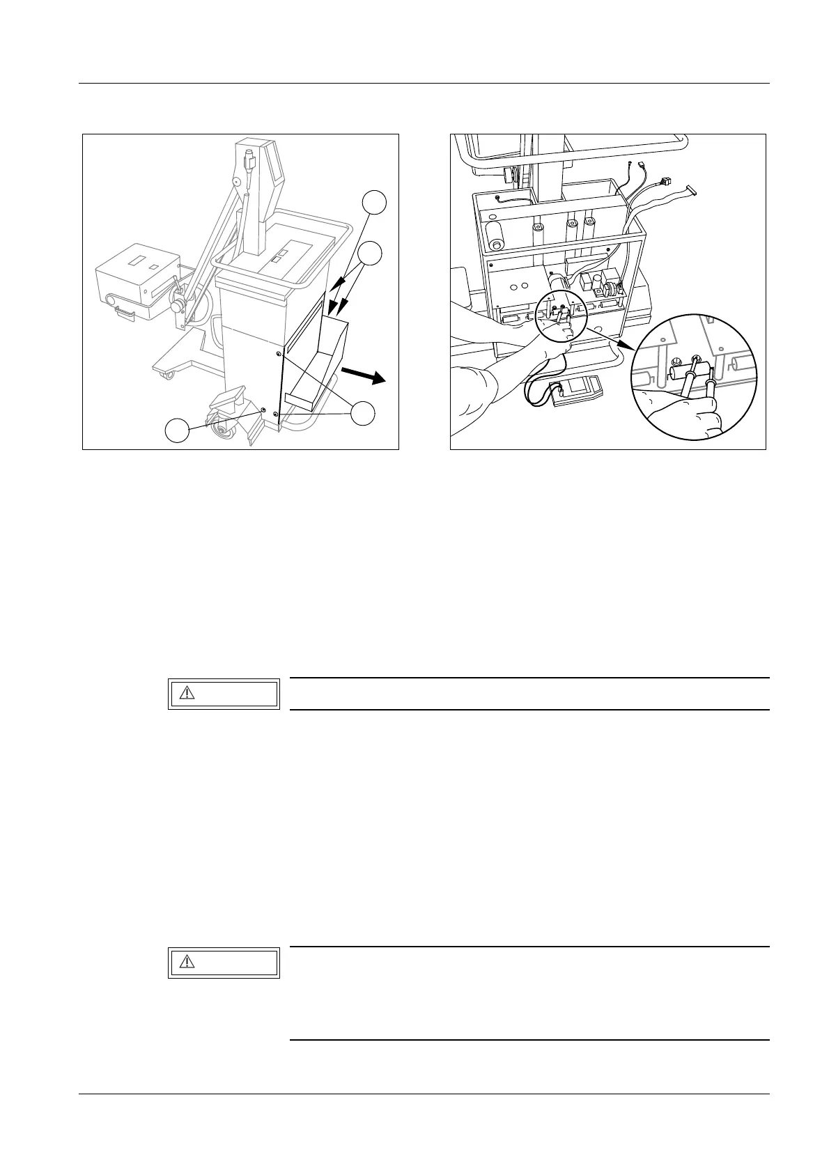
• Switch the unit off; disconnect the line voltage plug;
• Remove the 2 cover screws on each side (1/Fig.10) and remove the cover(with cassette
drawer).
• Measure the actual voltage present in the capacitor bank with the DVM at test point -
VCC and +VCC on the inverter board D960 or (more accessible) on the capacitor board
D970 at the + connecting point of the C3 capacitor and on the right-hand side of fuse F3
(see Fig. 11).
• Remove one cover screw on each side (2/Fig.10).
• Unscrew the three Allen screws (2/Fig.11).
• Pull out the connectors X3 and X9 (3/Fig.11) on the charging board D950.
• Remove flat ribbon cable X20 (4/Fig.11) from the inverter board D960 and from the
charging board D950.
• Disconnect and remove the cables of oscillating circuit capacitor C1 and oscillating
circuit coil L1 to inverter board D960.
• Pull the entire capacitor unit out towards the front.
Continue work only if the capacitor unit is discharged (U
< 10 V)
If a fuse on D970 is defective, high voltage may still be present at
the affected capacitor.
In this case, discharge the affected capacitor with the discharging
resistor R5 (5/Fig. 11) .
V
C
C
+
-
R
5
C
1
R
3
R
4
1
1
2
2
Fig. 10 Fig. 11
WARNING
WARNING