Prerequisites 1 - 3
Siemens AG SPR8-125.061.02 Page 3 of 4 POLYMOBIL Plus
Medical Engineering Rev. 01 01.00 TD SD 24
When working on the open system, there is the danger of
Electric shock
!
• The capacitor bank can still be charged.
Do not attempt to work on the system while this condition exists.
• After switching off the system, approximately 450 V may still be
present in the system ; even after disconnecting the line voltage
plug. Within 10 minutes this voltage will drop to approximately
10 V.
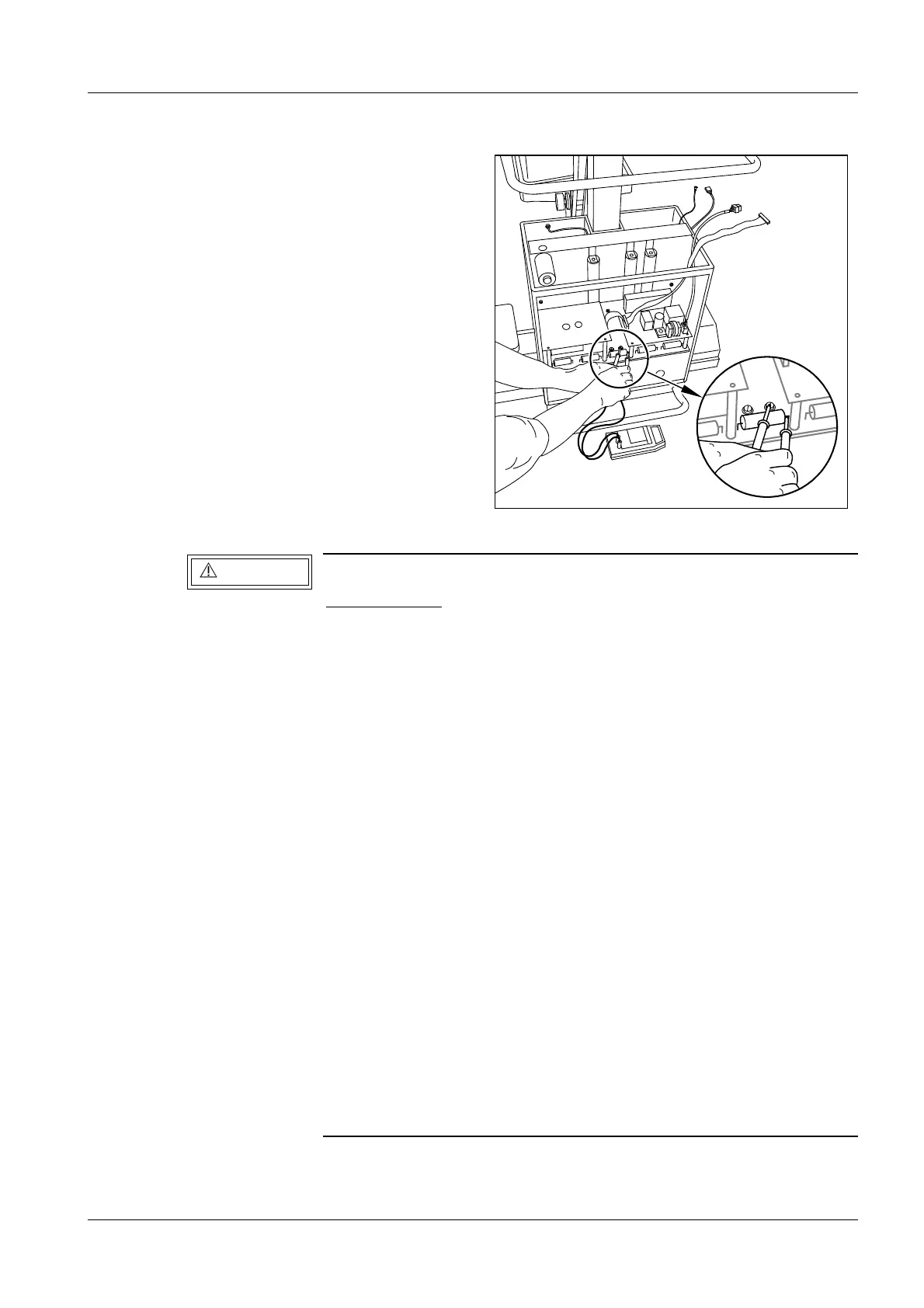
• Always measure the actual voltage present with the DVM at test
points -VCC and + VCC on the D 960 inverter board or (more
accessible) on the D 970 capacitor board at the + connection
point of capacitor C3 and on the right side of fuse F3 (refer to
Fig. 1).
• LED’s V1 ... V10 on D 970 go out at a significantly higher voltage
level and therefore they are not reliable safety indicators.
• If a fuse on the D 970 has responded, high voltage may still be
present at the affected capacitor even after a prolonged period
of time.
• The capacitor discharging circuit utilizes the D925 board, CS
and LS relays. If connectors X3 or X9 on D 925 or D 950 are not
inserted or if there is a defect in the circuit, the C-bank will not
discharge.
This can cause life-threatening voltage to be present in the
system even after a prolonged period of time.
• Refer also to chapter "Replacing the capacitor bank".
Fig. 1
V
C
C
+
-
R
5
C
1
R
3
R
4
WARNING