MAIN OPERATION PANEL | 17
2.5 Foot switch operation
(1) Foot switch for chucking
Foot switch has been installed to fix the workpiece on main
chuck.
Put a workpiece into the chuck, it will be fixed by stepping on the
foot switch once.
If the foot switch is stepped on again in the chucking state, it
becomes unchucking state.
This switch does not work during automatic operation, M31
command, spindle rotation and M-code (M68, 69) command.
2.6 LED display
(1) Chucking LED
1) This LED is to confirm the chucking of spindle.
ON ; indicates that switch(option) to check the clamp state of chuck
has been worked completely, and it is not the emergency stop
condition of spindle due to the malfunction of sensors related to
the chuck during the spindle rotation (Normal chucking
completion).
Flickering ; indicates that low pressure chucking state has been
occurred under the state of the chucking confirmation in
case of equipped with dual chucking(option), or abnormal
condition for spindle has been occurred due to the
malfunction of sensors related to chuck during the spindle
rotation.
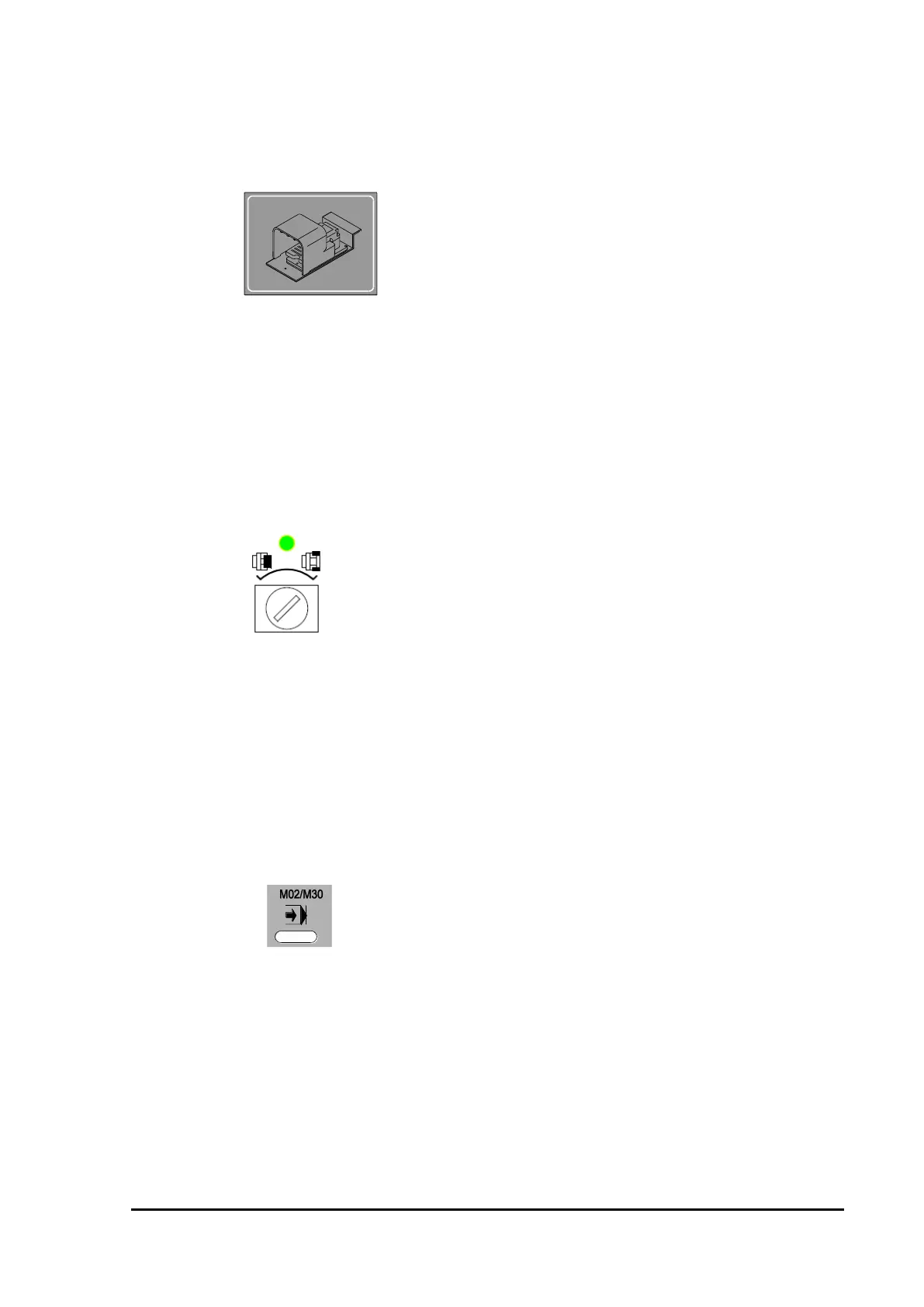
2) M02 / M30 LED
ON ; indicates when the program has been completed due to the
execution of M02 or M30 during the automatic operation.
※ This lamp is disappeared on the new operational panel.
Only valid for the old operation panel.
Icon display in machine screen.
 Loading...