Installing the Device
2.6Connecting the Failsafe Alarm Relay
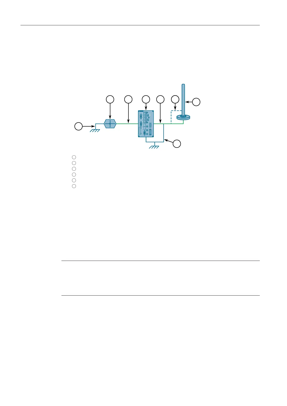
3. Using shielded coaxial cables, connect the antenna to either the ANT3 (SISO) or
ANT4 (MIMO) port on the device. Make sure the cable is routed away from any
noise sources, such as Switch-Mode Power Supplies (SMPS).
If needed, install a lightning protect between the antenna and the device.
1
Drain Wire
2
RUGGEDCOM RX1400
3
Shielded Coaxial Cable
4
Lightning Protector
5
Ground Wire
6
WLAN Antenna
Figure2.8 Antenna and Lightning Protector Assembly (Optional)
2.6 Connecting the Failsafe Alarm Relay
The failsafe relay can be configured to latch based on alarm conditions. The NO
(Normally Open) contact is closed when the unit is powered and there are no ac-
tive alarms. If the device is not powered or if an active alarm is configured, the relay
opens the NO contact and closes the NC (Normally Closed) contact.
Note
Control of the failsafe relay output is configurable through RUGGEDCOM RX1400.
One common application for this relay is to signal an alarm if a power failure oc-
curs. For more information, refer to the RUGGEDCOM RX1400 User Guide for the
RUGGEDCOM RX1400.
The following shows the proper relay connections.
RUGGEDCOM RX1400
Installation Manual, 09/2019, C79000-G8976-1103-13
21