4-59
System Manual
C79000-G8576-C199-06
12 2 2 2
3
4
56
7
DC Line
Monitor Output
24V DC
+ -
L+M
Disconnect
before removing
power supply!
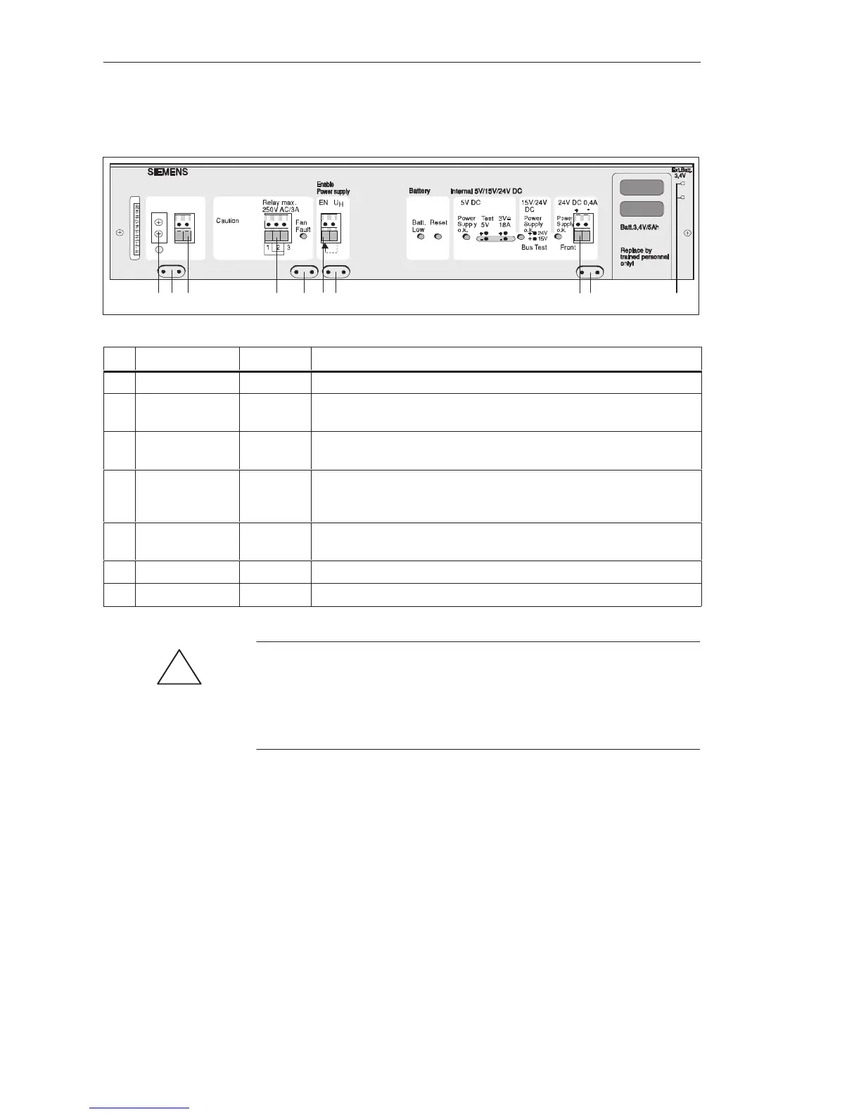
ID Label Element Purpose
1 Protective conductor terminal for PSU module and housing.
2 Strain reliefs for connecting cables, with metal contact surface for cable
shields.
3 DC Line Screw
terminals
System connection, 24 V input voltage
4 Monitor Output Relay
output
Standstill of one or both fans is signaled via LED and relay contact, and
results in shutdown of output voltages (can be shut down via jumper F-R of
the PSU; then only relay signal and LED indication).
5 Enable Power
supply
Input/
output
No voltage at the EN input results in shutdown of the PSU. Not more than
7 EN inputs may be driven with one U
H
output (front terminal).
6 DC 24 V; 0.4 A Output This output can be used to power the enable inputs of the U Periphery.
7 Ext.Batt. 3.4 V Sockets Sockets for external 3.4 V backup voltage.
!
Caution
Observe the appropriate VDE specifications, especially VDE 0100. The
terminals at the front are suitable for a conductor cross-section of up to
4 mm
2
, solid, or 2.5 mm
2
, flexible. Ensure adequate strain relief of the
connections.
You can add a 15 V auxiliary submodule to the 6ES5 955-3NA12 power
supply unit (for example, if you wish to use SINEC H1). The auxiliary
submodule produces a stabilized 15 V output voltage from the 24 V output
voltage. The auxiliary submodule is short-circuit protected. The output
voltage is monitored. If the voltage is too low, the green “15/24 V o.k.” LED
on the front plate goes off. If the voltage is too high, the output is
short-circuited by a thyristor.
Terminals
15 V Auxiliary
Submodule
Central Controllers and Expansion Units Power Suppl
Unit
 Loading...

