8-4
System Manual
C79000-G8576-C199-06
8.1.1 Design
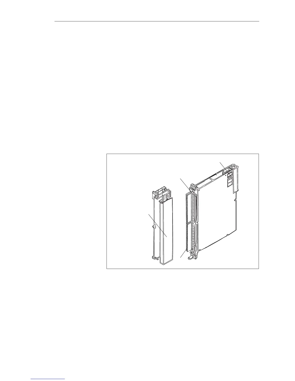
The modules are designed as plug-in PCBs for central controllers and
expansion units with backplane connector and with a blade connector to
accept a plug-in front connector. The front connector has screw or crimp
terminals and is available separately; you can connect the process signal lines
to it directly.
Fitted to each module is a strip with green LEDs to indicate the logic states
of inputs or outputs. The LEDs are arranged in bytes and marked bit 0 to 7.
Output modules for direct voltage additionally have red LEDs to indicate
short-circuits between output lines and ground (L-) within a group. Output
modules for alternating voltage have red LEDs to indicate a fuse failure.
Fitted on each module is an addressing switch with six, seven or eight
rockers to set the module address.
The modules are protected on both sides by covers.
Front Connector
LEDs
Blade Connector
Addressing Switch
Figure 8-1 Digital Input Module
LED Indicators
Addressing Switch
Di
ital Input/Output Modules
 Loading...

