3-26
System Manual
C79000-G8576-C199-06
3.4.3 Connecting Non-Floating or Floating Modules
Shown in the following sections are the specical features when installing
non-floating and floating modules.
In an installation with non-floating modules, the reference potentials of the
control circuit (0 V
int
) and load circuits (0 V
ext
) are electrically connected.
The reference potential of the control circuit (0 V
int
) is given by the PE or
protective conductor terminal and must be connected to the reference
potential of the load circuit via an externally laid conductor.
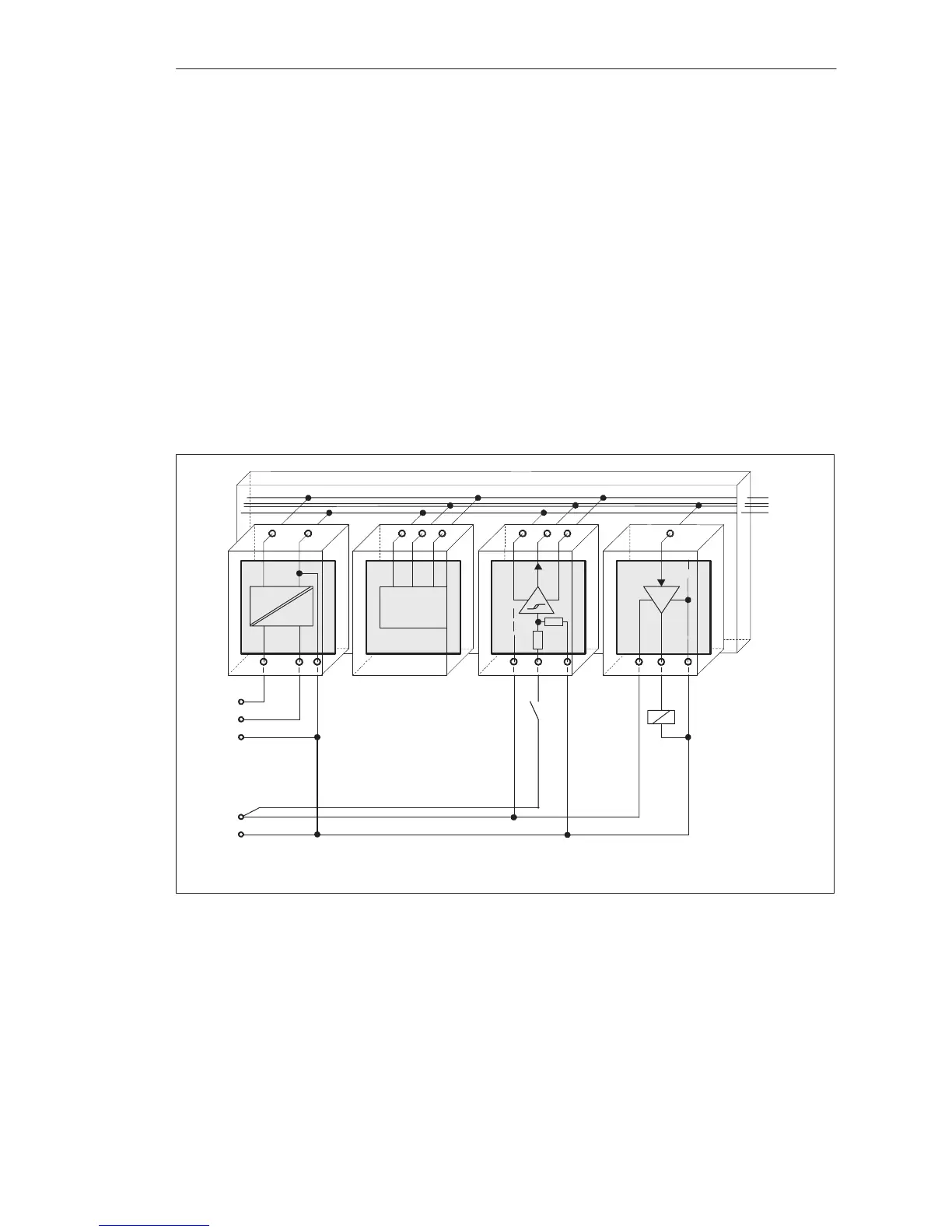
Shown in the following figure is a simplified installation with non-floating
modules. The arrangement is independent of the grounding concept. The
connections for grounding are therefore not drawn.
1L+
1L–
PE
Control Power
Supply
2L+
2L–
DC 24 V Load Power Supply
External Connection for a
Standard Reference Potential
PS
CPU
DI
DQ
Data
0 V
U
int
Figure 3-11 Simplified Representation of an Installation with Non-Floating Modules
The voltage drop on line must not exceed 1 V. Otherwise there will be a
shift in reference potentials resulting in module malfunctions.
Installation with
Non-Floating
Modules
Installation Guidelines
 Loading...

