10-2
System Manual
C79000-G8576-C199-06
10.1 Application
The monitoring module can be used in the expansion units of the
programmable controllers S5-115U, S5-135U and S5-155U.
The module monitors the data bus, the address bus and the control signals
MEMW/, MEMR/ and RDY/. Faults are displayed via four red LEDs on the
front panel. A group signal is output at the same time via a floating contact.
Following a fault, the module can be reset by means of the RESET key on
the front panel or the RESET input (see Section 10.2.3).
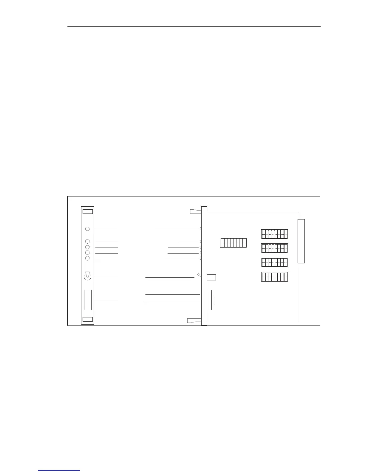
10.1.1 Design
The monitoring module is designed as a plug-in PCB in double Euroformat
with a 32-pin backplane connector for the S5 bus.
A connector for the relay contact and RESET input as well as one green
LED, four red LEDs and a RESET key are located on the front panel.
Operation (green LED)
Command output inhibit (red LED)
Control signal fault (red LED)
Address bus fault (red LED)
Data bus fault (red LED)
RESET input
Relay contact
RESET key
RUN
BASP
R/W
ADB
DB
12345678
S1
S2
S3
S4
S5
12345678
12345678
12345678
12345678
X4
1
6
Bus
PESP
QVZ
125ms
250ms
500ms
1s
1
2
4
8
16
32
64
128
ON
OFF
ON
OFF
ON
OFF
ON
OFF
ON
OFF
Figure 10-1 Location of the Coding Switches
Monitorin
Module
 Loading...

