4-22
System Manual
C79000-G8576-C199-06
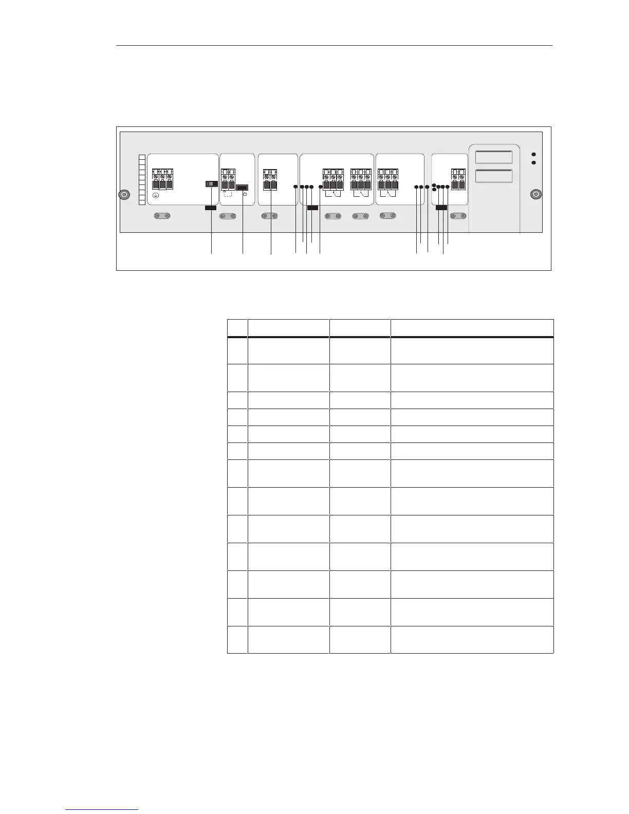
Apart from the jumpers, the LEDs and controls of the power supply unit are
fitted on the front plate. The following figure shows their locations:
6ES5955-3LF42
L1
N
12
3
4
5
67 8
9
10 11 1412 1513 16 17 18
+
+
+
+
–
–
–
–
AC120V4,5A
AC230V2,6A
CAUTION!
Disconnect
before
removing
power supply!
Voltage
selector
Unlock
Fan 1
Unlock
Fan2
Unlock
Fan3/Res.Batt
.
Input
DC 24V Ext.
AC line 50/60 Hz
Enable
Power supply
Voltage Monitor
Fan
Battery
Ext.Batt.
DC 4,5V
Fault
Warning Alarm
Warning
max. AC 250V/3A
max. AC 250 V/ 3A
Voltage low
Fan1
MB low
Fan2
RB low
5Vo.k.
Fan3
Reset
Alarm
EN UH
Power
I
I
1234
5
6
7
89
10
Batt. 3,6V/5Ah
Replace by
trained personnel
only!
Use battery holder
C98100-A1155-B21
only!
SIEMENS
Output
DC 24V 2,8A
DC 5/15/24V
Internal
3V=40A
15Vo.k.
24Vo.k.
Batt.+Fan
G
D
A
H
IF
B
C
L
K
J
M
E
The labelling and purpose of the LEDs and controls are given in the
following table:
ID Label Element Purpose
A Voltage
selector
1)
Switch Voltage selector switch:
choice of 120 V or 230 V
B Power Switch Standby On/Off switch (not system
On/Off switch)
C Voltage low Red LED Low voltage at load voltage monitor input
D Fan 1 Red LED Failure of Fan 1
E Fan 2 Red LED Failure of Fan 2
F Fan 3 Red LED Failure of Fan 3
G Alarm Red LED Indicates failure of at least two fans of
insufficient air flow
H MB low Yellow LED Lithium battery/external battery voltage
below preset limit (3V)
I RB low Yellow LED Rechargeable battery voltage below preset
limit (3V)
J Reset Batt.+Fan Pushbutton Reset of LEDs D, E, F, G, H, I when fault
cleared
K 5V o.k. Green LED Lights up to indicate output voltage
within permissible range
L 15V o.k. Green LED Lights up to indicate output voltage
within permissible range
M 24V o.k. Green LED Lights up to indicate output voltage
within permissible range
1)
Only on the 6ES5 955-3LC42 and 6ES5 955-3LF42
LEDs and Controls
Central Controllers and Expansion Units Power Suppl
Unit
 Loading...

