10-7
System Manual
C79000-G8576-C199-06
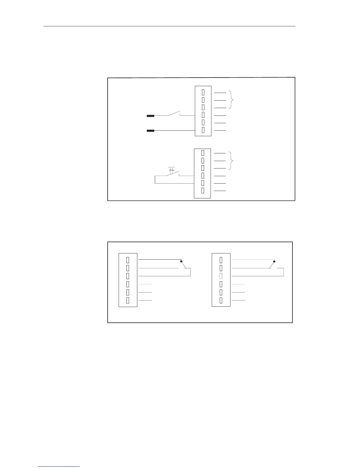
10.2.3 Connecting the RESET Input
4
5
6
3
2
1
Relay contact
RESET input
L+ (24V)
L–
L+
L–
4
5
6
3
2
1
Relay contact
RESET input
L+ (24V)
L–
RESET input (floating) with external 24-V supply
RESET input (floating) with internal 24-V suppy
10.2.4 Switch Positions of the Relay Contact
4
5
6
3
2
1
4
5
6
3
2
1
Contact not actuated (idle) or fault
Contact 1-3 closed Contact 1-2 closed
Contact actuated (operational)
10.2.5 Installation Guidelines
The module is to be wired according to the VDE regulations 0100, 0110 and
0160.
Detailed information on power supply, cabinet design, cabinet ventilation,
cabinet wiring and protective measures can be found in Chapter 3.
Monitorin
Module
 Loading...

