8-20
System Manual
C79000-G8576-C199-06
8.2.3 Marking of Modules
For the marking of modules and front connectors, a set of labels is supplied
with the modules for the labeling, and a set of labels with the addresses is
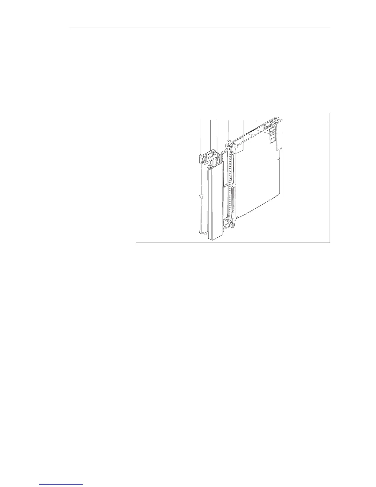
supplied with the central controller. Figure 8-9 shows the locations of the
labels. The self-adhesive address label is pre-printed. You can mark the strips
to identify the signal line terminals.
5
1
13
4
2
Figure 8-9 Marking and Labeling of Modules
1 Address label with the module address (output byte QB n or input byte IB n) under
which the module is addressed by the STEP 5 program (address labels are supplied
with the PLC), and for marking the addressing switch settings
2 Labeling strip with the product designation which is color-coded to distinguish
between the various module types, as well as fields to mark the version and for
user-related labeling of channels.
Color codes:
Digital inputs for DC voltage blue
Digital inputs for AC voltage red
Digital outputs for DC voltage green
Digital outputs for AC voltage orange
Update the version when replacing modules!
3 Label with module address and marking of the required settings for the addressing
switch
4 Labeling strip for terminal designations or connection diagrams for the front connector
5 Name plate
Di
ital Input/Output Modules
 Loading...

