8-19
System Manual
C79000-G8576-C199-06
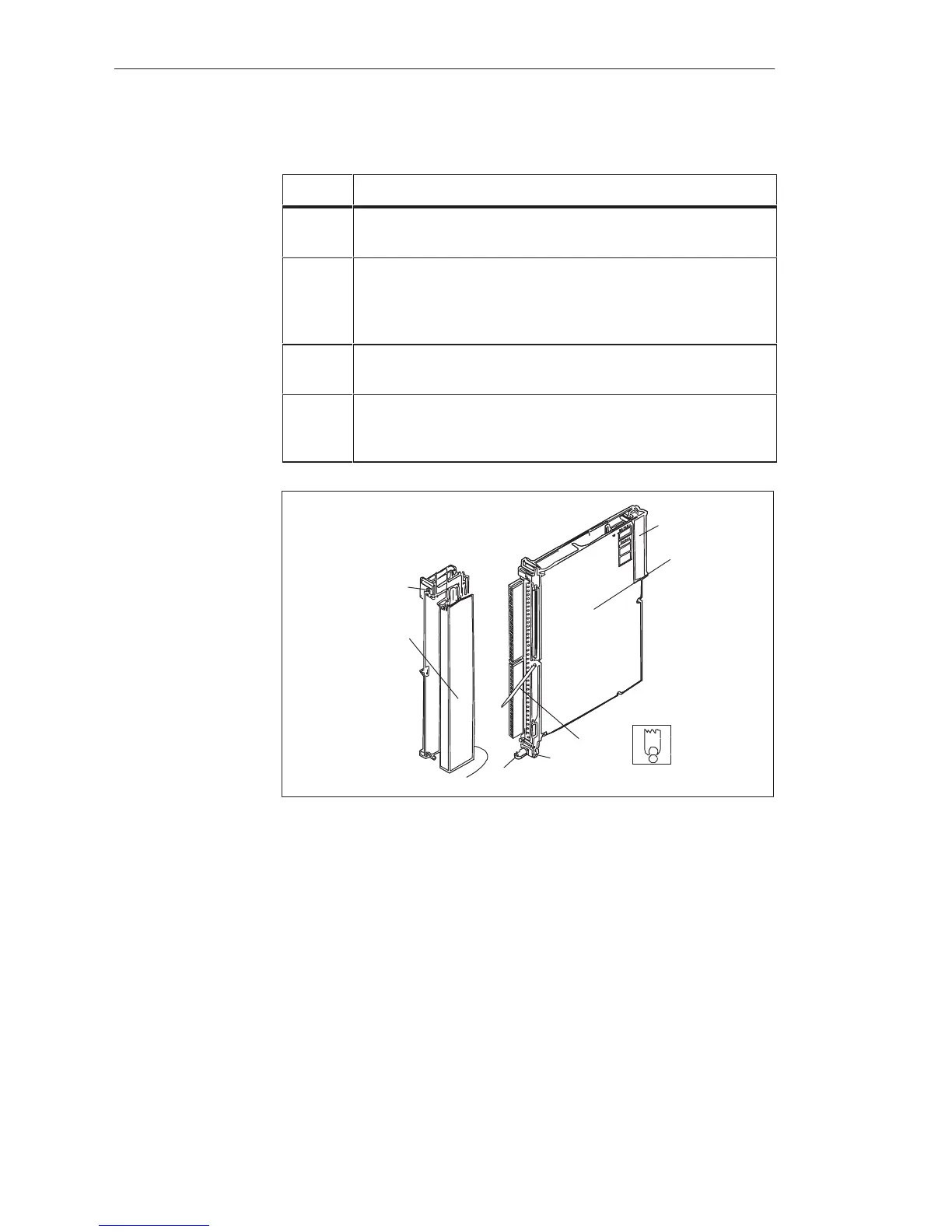
Remove a digital input/output module as follows:
Step Action
1
Release the upper locking bar on the subrack and swivel it up-
wards and out.
2
Slacken the screw in the upper part of the front connector.
This causes the front connector to be pressed out of the female
connector of the module. Contacts F+ and F- of the enable in-
put at the upper end of the front connector are thus opened first.
3
Swing the front connector out and lift it away from the support
pin of the module.
4
Release the module, if necessary, by rotating the locking pin by
90
o
. You can pull the module out of the subrack with a grip
which swivels outwards.
1
2
3
5
6
4
Module
Front Connector
Support Mount
Support Pin
Figure 8-8 Module with Front Connector
1 Screw
2 Locking pin
3 Support mount
4 Support pin
5 Grip
6 Backplane connector
Comply with VDE Specifications 0100 and 0160 to carry out the wiring of
the supply and signal lines which are to be connected to the programmable
controllers and front connectors of the modules. Detailed information on the
supply of power, cabinet assembly, cabinet ventilation, cabinet wiring and
protective measures can be found in Chapter 3.
Wiring
Di
ital Input/Output Modules
 Loading...

