9-66
System Manual
C79000-G8576-C199-06
9.5.10 Broken Wire Signal for Resistance Thermometers
An open-circuit in the lines to a resistance thermometer is indicated as
follows:
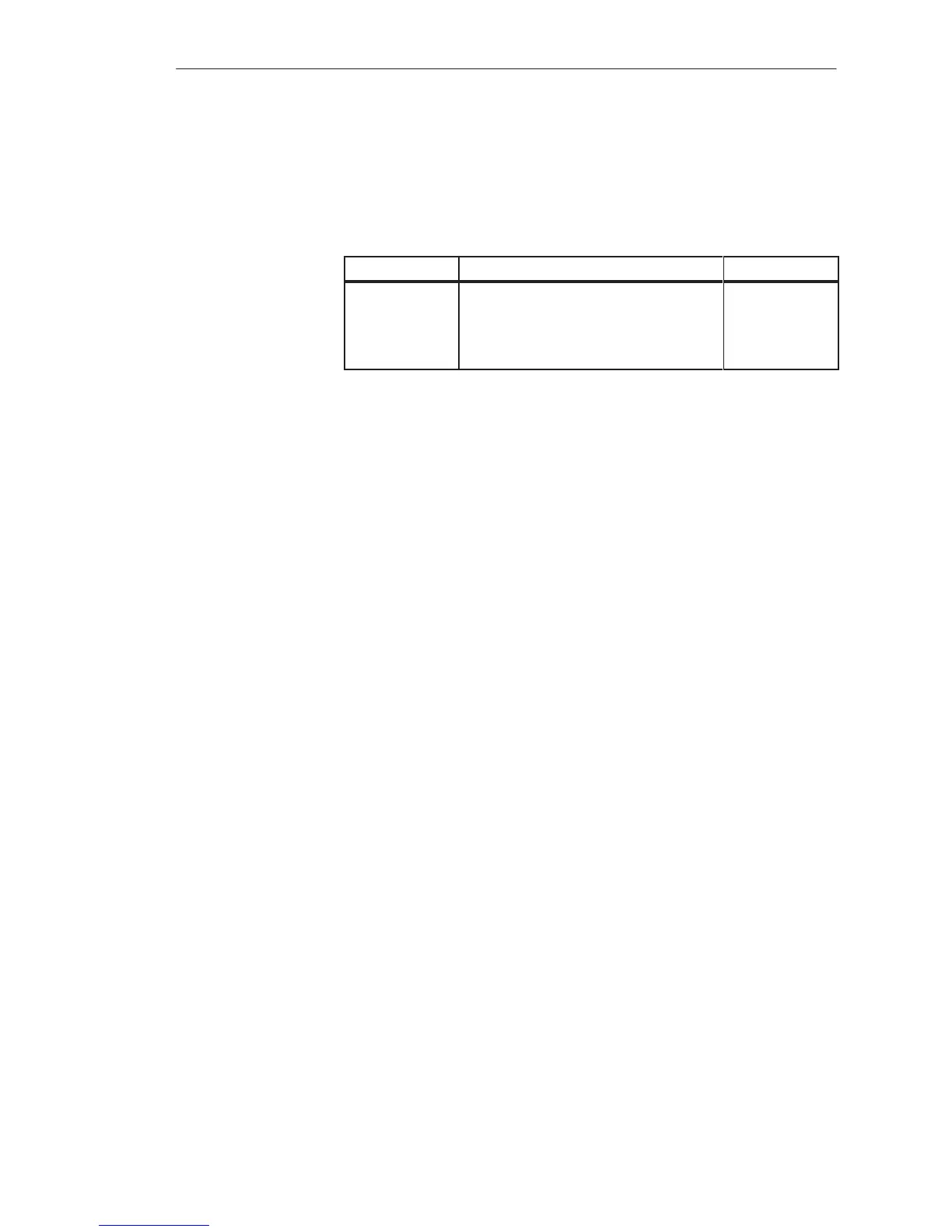
Broken Wire at Module Reaction, Encoded Value Error Bit E
M+
M–
Pt 100
I
C+
I
C–
0
0
0
0
0
1
1
1
1
1
If the mode “without broken wire signal” is selected on the module, an
open-circuit of the resistance thermometer is indicated with an overflow.
Unassigned channels can be used for voltage or current measurement if the
current flow outputs relating to the particular measuring channel are shorted
with a wire jumper. Without this jumper, the error bit would be set for this
channel and the value 0 would be encoded.
When set to “resistance thermometer,” switch 7 of mode switch I of the 465
analog input module allows broken wire monitoring of the I
C+
lines to the
resistance thermometer (Pt 100 constant current supply). In the event of
open-circuit of this line, the error bit is set as for the other lines.
At the “voltage/current” (mV/mA) setting, the I
C+
lines are not monitored for
broken wire. (The error bit is not set for an open-circuit of this line.) You
should choose this switch setting if you exclusively measure voltages or
currents.
Broken Wire
Monitoring
Analo
Input/Output Modules
 Loading...

