8-21
System Manual
C79000-G8576-C199-06
8.2.4 Connecting the Signal Lines
The modules have 20 or 42-way blade connectors with contact blades
measuring 2.4 x 0.8 mm. Front connectors for 20 and 40 mm mounting width
with crimp connection and 40 mm mounting width with screw connection are
provided to connect the signal lines (screwdriver blade width: 3.5 mm,
maximum torque: 0.8 Nm).
Use stranded conductor to facilitate handling of the front connector.
When the crimp contact is inserted in the plastic body of the front connector,
a click can clearly be heard. This indicates that the contact is engaged. For
jumpering or to correct the wiring, you can remove the contacts with a
releasing tool (see ordering information) without having to pull out the front
connector.
Ferrules are not required for screw connections, because the screw terminals
are provided with wire protection. You can use ferrules of 7 mm in length to
DIN 46228. The maximum terminal area is 2 x 2.5 mm
2
.
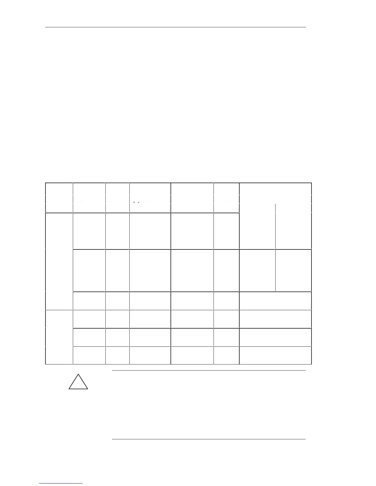
Terminal
Connector
Max.
Cross-Sec. of
-
Connector for
Front
-
Module 6ES5-
ype
ype
497-
o. o
Con-
gna
or
up-
ply Conductor
a
e
o
age
on-
nector
For Operation
tacts
Width
With Fan Without Fan
Crimp
Connec-
tion
4UA12 42 0.5 to 1.5 mm
2
5 to 60 V DC 20 mm 420. 430.
431, 432.
434, 441,
451, 454-14,
458
–
4UA22 42 0.5 to 1.5 mm
2
5 to 60 V DC 40 mm 453, 454, 457 420. 430.
431, 432.
434, 441,
451, 453,
454, 457,
458
4UA42 20 0.5 to 1.5 mm
2
24 to 230 V AC 40 mm 435, 436, 455, 456
Screw
Connec-
4UB12
4UB32
42 0.5 to
2 x 2.5 mm
2
5 to 60 V DC 40 mm
20 mm
420. 430. 431, 432. 434, 441,
451, 453, 454, 457, 458
on
4UB22 25 0.5 to
2 x 2.5 mm
2
5 to 60 V DC 40 mm 454
4UB42 20 0.5 to
2 x 2.5 mm
2
24 to 230 V AC 40 mm 435, 436, 455, 456
!
Caution
Only extra-low voltage v 60 V DC with safety separation from system
voltage may be used for the 24 V DC supply and for the 24 V DC input
signals. Safety separation can be implemented to the requirements of,
amongst other sources, VDE 0100 Part 410/HD 384-4-41/IEC 364-4-41
(as functional extra-low voltage with safety separation) or
VDE 0805/EN 60950/IEC 950 (as safety extra-low voltage SELV) or
VDE 0106 Part 101.
Di
ital Input/Output Modules
 Loading...

