3-27
System Manual
C79000-G8576-C199-06
Note
For 24 V DC digital output modules with electronic short-circuit protection,
you must ensure that the reference potential of the load power supply is
connected to terminal L- of the module. If this connection is missing (e.g.
open-circuit), a typical current of 15 mA can flow at the outputs. This output
circuit is sufficient
to prevent energized contactors or relays from being released
and to energize high-resistance loads (e.g. miniature relays).
With floating modules the control circuit and load circuit are metallically
isolated.
An arrangement with floating modules is required
for all AC load circuits and
for DC load circuits which cannot be coupled. The reasons are, for
example, different reference potentials of the sensors or grounding of the
positive terminal of a battery.
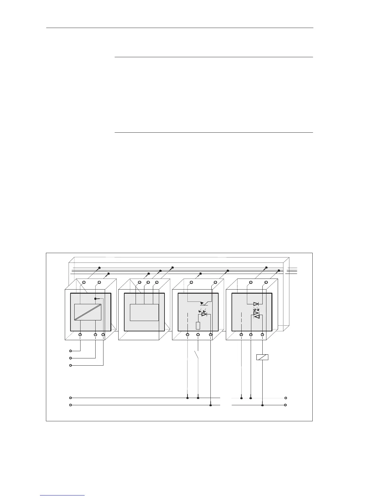
Shown in the following figure is a simplified installation with floating
modules. The arrangement is independent of the grounding concept. The
connections for grounding are therefore not drawn.
1L+
1L–
PE
24 V DC Control Power Supply
2L+
2L–
24 V DC Load Power Supply
PS
CPU
DI DQ
Data
0 V
U
int
L1
N
230 V AC Load Power Supply
Figure 3-12 Simplified Representation of an Arrangement with Floating Modules
Installation with
Floating Modules
Installation Guidelines
 Loading...

