4-73
System Manual
C79000-G8576-C199-06
The following applies to selecting the cables for the terminals:
Terminals Cabling Max. Permissible Cable
Cross-Sections
Power supply AC line Phase L 1 4 mm
2
solid or 2.5 mm
2
flexible
Neutral N 4 mm
2
solid or 2.5 mm
2
flexible
Protective conductor 4 mm
2
solid or 2.5 mm
2
flexible
Relay terminals, also suitable
to 230 V AC / 3 A
4 mm
2
solid or 2.5 mm
2
flexible
For installing and removing the fan submodule, refer to the instructions in
Section 4.3.2 on the power supply unit. These also apply in principle here.
FFor wiring up the fan submodule, refer to the instructions in Section 4.3.2
on the power supply unit. These also apply in principle here.
The fan submodule is switched on when the line voltage for the central
controller or expansion unit is switched on.
!
Caution
If you have set the voltage selector switch on the -3LA11 to 120 V, but the
actual voltage value is 230 V, the fan submodule may be damaged when line
voltage is switched on.
Fan submodule faults are indicated via relay contacts (“Monitor Output”) and
an LED.
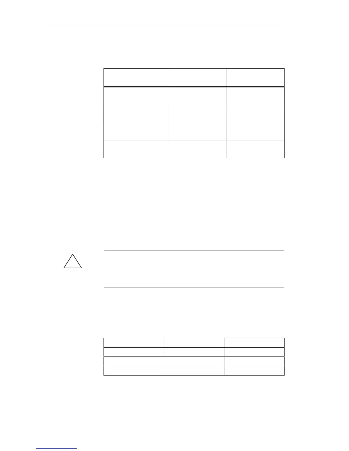
The following table shows when the relay contacts are open or closed:
Fan Submodule Relay Contact 1-2 Relay contact 2-3
Switched off open closed
In normal operation closed open
During fault open closed
In the case of a fault, the red LED “Fan Fault” lights up.
Selecting Cables
Installing and
Removing the Fan
Submodule
Wiring up the Fan
Submodule
Switching on the
Fan Submodule
for the First Time
Fault Indications/
Fault Diagnostics
Central Controllers and Expansion Units Power Suppl
Unit
 Loading...

