5-119
System Manual
C79000-G8576-C199-06
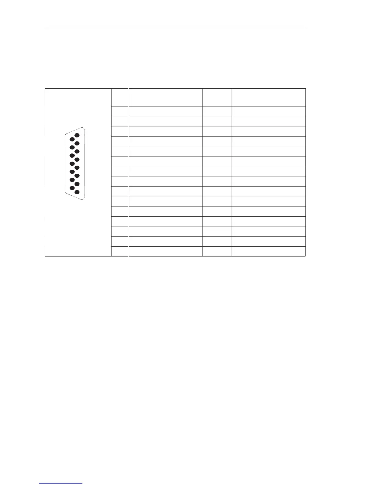
Shown in the following figure are the pin assignments of the 15-pin
subminiature D-type connector in the front plate of the SINEC L1
submodule:
Pin Designation Current
Direction
Remarks
1 Housing/GND/GND
ext
2 – RxD ³
8
3 VPG + 5 V_
15
4 + 24 V from bus
5 24 V ground
6 + TxD ²
7 – TxD ³
8 Housing/GND/GND
ext
9
9 + RxD ²
10 24 V ground ² Current return
11 20 mA ³ Current source, transmitter
12 24 V ground
13 20 mA ³ Current source, receiver
14 VPG + 5 V_
15 24 V ground
²: from partner to CPU
³: from CPU to partner
Pin Assignments
of the SINEC L1
Submodules
CPUs, Memor
Cards, Memor
Submodules, Interface Submodules
 Loading...

