6-4
System Manual
C79000-G8576-C199-06
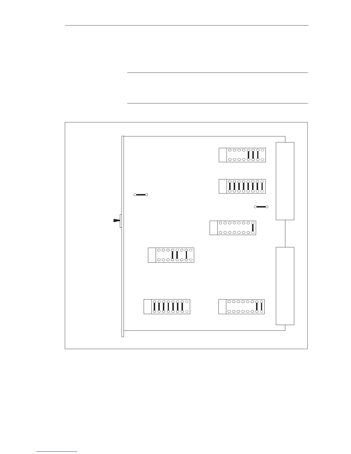
Shown in Figures 6-1 and 6-2 are the locations of jumpers and switches on
the modules, at which the settings required for startup must be made.
Note
The settings of jumpers which are not described in the following text must
not be changed.
X1
X2
EP 2
EP 7
EP 63
EP 62
EP 43
EP 45
J2
J1
Mode Switch
(RUN,STOP,TEST)
16 9
8
1
16 9
8
1
1
16 9
8
16 9
8
1
16 9
8
1
8
16 9
1
Figure 6-1 Location of Jumpers on the 923A Coordinator (when Delivered)
Setting the
Jumpers
Multiprocessor Operation/Coordinators
 Loading...

