6-22
System Manual
C79000-G8576-C199-06
Station numbers are assigned to all the modules to be served by the
multiplexer in the unit. These numbers must be within the range 1 to 31
(decimal). You set the lowest of these numbers, the base address, with DIL
switch S2 in binary code. The maximum of eight numbers are allocated to
the slots of the PLC (see following table).
All eight numbers or slots are assigned to switch S3: the lowest number to
switch S3.1, and the highest number to switch S3.8. The setting of station
numbers and the base address are described in more detail in Section 6.5.2.
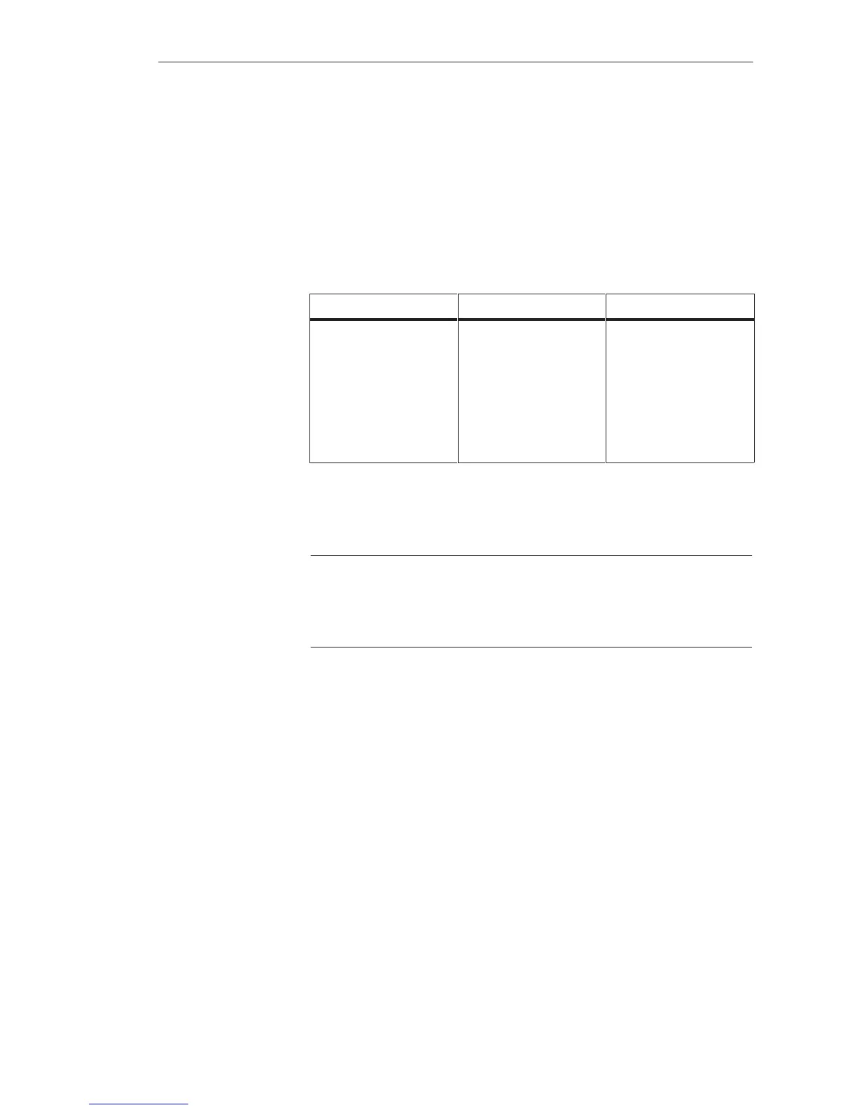
Switch Slot Station No.
S3.1
S3.2
S3.3
S3.4
S3.5
S3.6
S3.7
S3.8
11
27
43
59
75
83
91
99
Base address
Base address + 1
Base address + 2
Base address + 3
Base address + 4
Base address + 5
Base address + 6
Base address + 7
If slots are not occupied or if you wish to operate modules via their own front
connectors, you must delete the numbers assigned to the corresponding slots
with switch S3.
Note
For a module operated via the multiplexer, the front connector of the PG
interface of the CPU must not be plugged in. With CPUs 948 and 928B,
this only applies to the integrated PG interface SI 1.
Selection Method
for the Serial
Interfaces
Multiprocessor Operation/Coordinators
 Loading...

