8-11
System Manual
C79000-G8576-C199-06
Only the flag word (FW) may be accessed during the cyclic program.
Accessing the I/O bytes in the process image will result in alarm loss.
Addressing of the module must therefore be above address 127. Double
accessing of I/O bytes, even from different CPUs, is not permissible (alarm
loss).
The four I/O bytes of a module must be scanned successively and in
ascending order. The scanning of byte n inhibits the input circuit of the
module, and the scanning of byte (n + 3) enables them again.
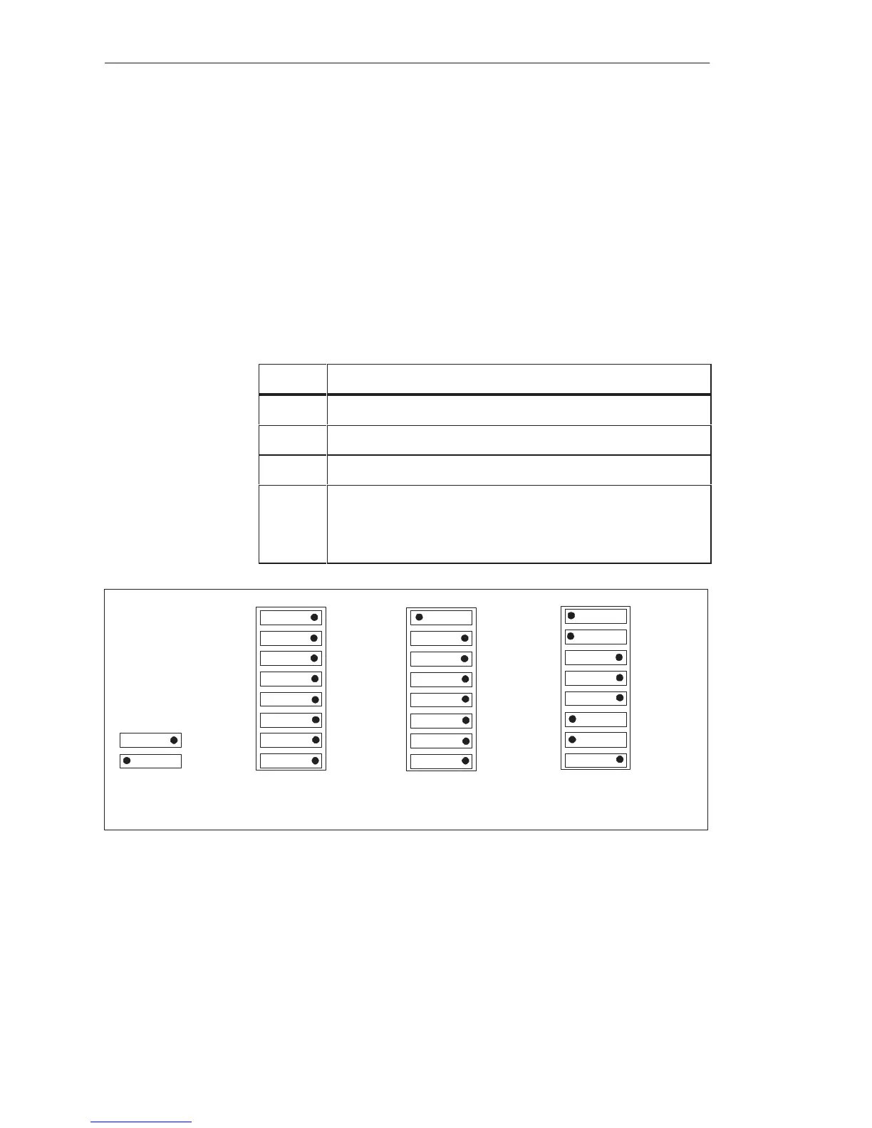
Make the following settings on the module to operate it with a process alarm
via IB 0:
Step Action
1 Insert jumpers X3 and X4
2 Set switch row S1 to Off.
3 Set bit 0 on switch row S2 to On, and all other switches to Off.
4 Set switch row S3 to choose whether the interrupt is to be initi-
ated with a positive-going (leading) or negative-going (trail-
ing) edge. The setting of a pair of switches applies to an entire
byte.
S1
3
3
3
Bit 3
IR-D
4
4
4
Bit 4
IR-E
5
5
5
Bit 5IR-F
6
6
6
Bit 6IR-G
7
7
7
Bit 7INT
0
0
0
Bit 0IR-A
1
1
1
Bit 1IR-B
2
2
2
Bit 2IR-C
S2
S3
Byte 0
Byte 1
Byte 2
Byte 3
}
}
}
}
:OFF
:ON
Byte 0: Positive-Going Edge
Byte 1: Negative-Going Edge-
Byte 2: Both Edges
Byte 3: No Process Interrupt
Figure 8-5 Switch Settings for Operation with Process Alarm via IB 0 (Example)
Settings on the
Module
Di
ital Input/Output Modules
 Loading...

