8-32
System Manual
C79000-G8576-C199-06
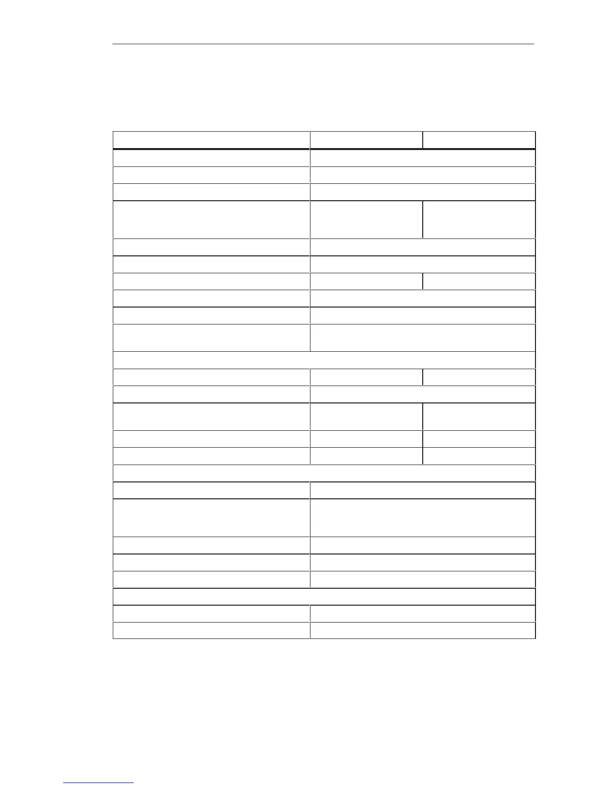
8.4.2 6ES5 430-4UA13/4UA14 Digital Input Module
–4UA13 –4UA14
Rated input voltage 24 V DC
Number of inputs 32
Isolation Yes, 1 group with 32 inputs
Input voltage
for logic 0
for logic 1
1)
–3 to 7 V
13 to 33 V
–33 to 7 V
13 to 33 V
Rated input current 7.0 mA
Input frequency 100 Hz max.
Delay time 4 ms typical (2.5 to 6.5 ms) 3 ms typical (1.4 to 5.0 ms)
Input resistance 3.3 kilohms typical
Coincidence factor (total load capability) 100 %
Permissible line length 600 m max., unshielded;
1000 m max., shielded
Power supply
Digital section from system bus 5 V, 100 mA typical 5 V, 30 mA typical
Supply voltage for 2-wire BERO 22 to 33 V
Supply voltage L+/L– 24 V (20 to 30 V) L+ to terminal 3 not re-
quired
Current consumption from L+/L– Approx. 100 mA L+ not required
Power dissipation (rated operation) 8.3 W 5.6 W
Enable input (F+/F–)
Rated input voltage 24 V DC
Input voltage
for logic 0
for logic 1
–33 to 5 V
13 to 33 V
Rated input current 5 mA
Permissible line length 200 m max.
Voltage test to VDE 0160 Between group and ground point: 1250 V AC
Mechanical specifications
Dimensions (W x H x D) 20 mm x 255 mm x 195 mm
Weight Approx. 0.4 kg
1)
Polarity reversal for up to 8 inputs per module is permissible.
Di
ital Input/Output Modules
 Loading...

