8-54
System Manual
C79000-G8576-C199-06
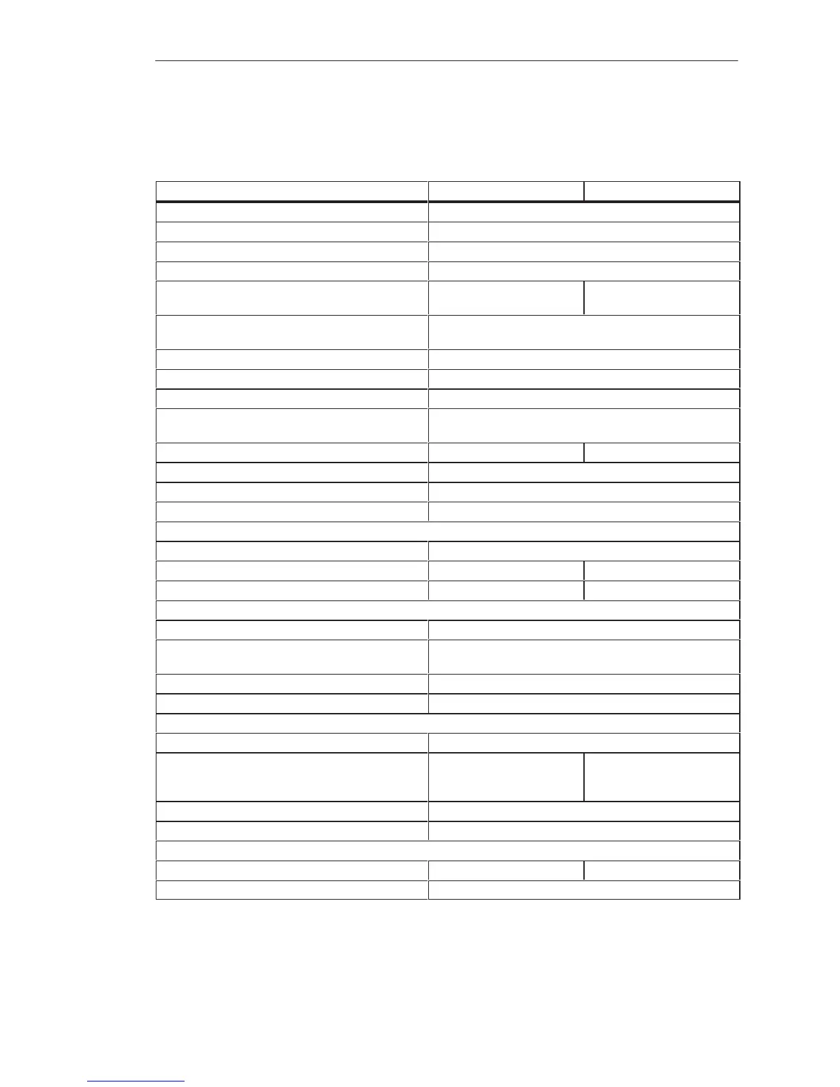
8.4.12 6ES5 454-4UA13/4UA14 Digital Output Module
–4UA13 –4UA14
Rated supply voltage L+ 24 V DC
Number of outputs 16, short-circuit protected
1)
Isolation Yes, 1 group of 16 outputs
Range for supply voltage 20 to 30 V DC
Fusing 6.3 A, slow
1 fuse per 4 outputs
7 A, fast
1 fuse per 4 outputs
Output voltage for logic 1
for logic 0
L+ – 2 V min.
3 V max.
Switching current (resistive, inductive load) 10 mA to 2 A
2)
Residual current at logic 0 1 mA max.
Switching current for lamps 0.45 A max. (10 W)
Switching frequency with resistive load
with inductive load
100 Hz max.
0.2 Hz max. at 1 A; 0.1 Hz at 2 A
Breaking voltage (inductive) Limited to L+ – 47 V Limited to L+ –55 V
Total switching current 4 A max. per 4 outputs
Coincidence factor (total load capability) 50 %
Permissible line length 400 m max., unshielded
Power supply
Digital section from system bus 5 V, 100 mA typical
Current consumption from L+/L– 24 V, 100 mA typical 24 V, 120 mA typical
Power dissipation (rated operation) 17.5 W 10 W
Enable input (F+/F–)
Rated input voltage 24 V DC
Input voltage for logic 1
for logic 0
13 to 33 V
– 33 to 5 V
Rated input current 5 mA
Permissible line length 200 m max.
Short-circuit monitoring
Indicator for signaling output (H+) Red LED for 4 outputs
Output voltage , referred to L–
(with feed at 1L+) for logic 1
for logic 0
1L+ – 5 V min.
3 V max.
1L+ –1,5 V min.
Switching current 10 mA max., limited
Voltage test to VDE 0160 Between group and ground point: 1250 V AC
Mechanical specifications
Dimensions (W x H x D) 40 mm x 255 mm x 195 mm 20 mm x 255 mm x 195 mm
Weight Approx. 0.55 kg
1)
Short-circuit protection responds with line resistance v 4,75 ohmd, irrelevant for the –4UA14.
2)
One digital input is permissible as minimum load.
Di
ital Input/Output Modules
 Loading...

