8-62
System Manual
C79000-G8576-C199-06
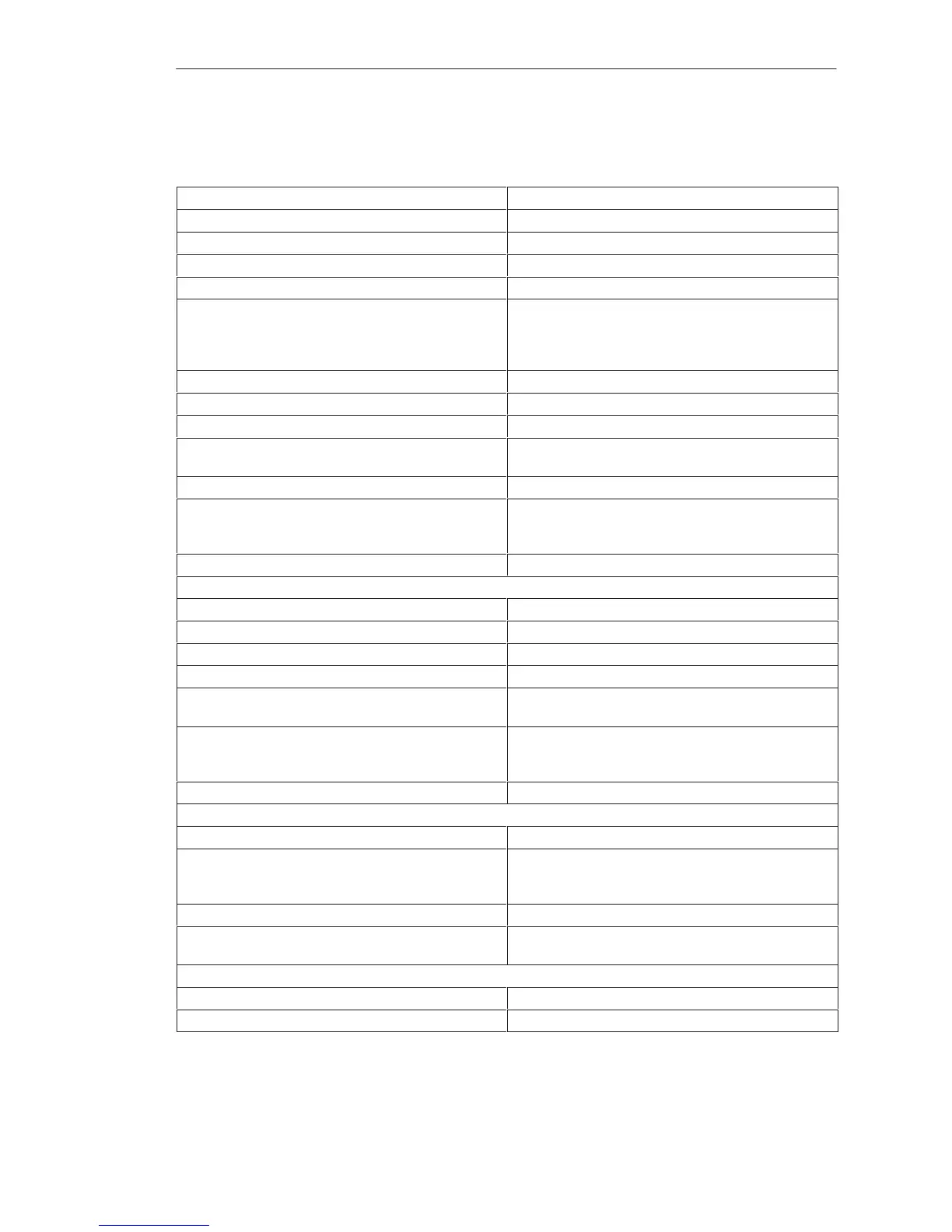
8.4.16 6ES5 457-4UA12 Digital Output Module
Rated supply voltage L+ 24 to 60 V DC
Number of outputs (decoupled via diodes) 16, short-circuit protected
1)
Isolation Yes, 16 outputs
Range for supply voltage 20 to 72 V DC
Fusing 16 x 1 A, slow
Output voltage for logic 1: (L+)-Switch
(L–)-Switch
for logic 0: (L+)-Switch
(L–)-Switch
L+ – 2.5 V min.
2.5 V max.
3 V max.
L+ – 3 V min.
Switching current (resistive, inductive load) 5 mA to 0.5 A
2)
Residual current at logic 0 1 mA max.
Switching current for lamps 0.22 A max. (5 W)
Switching frequency with resistive load
with inductive load
100 Hz max.
2 Hz max. at 0.5 A
Breaking voltage (inductive) Limited to L+ – 75 V
3)
Coincidence factor (total load capability)
ventilated
not ventilated
100 %
50 %; 100 % up to 35
o
C
Permissible line length 400 m max. unshielded
Power supply
Digital section from system bus 5 V, 120 mA typical
Power dissipation (rated operation) 13.0 W
Enable input (F+/F–)
Rated input voltage 24 to 60 V DC
Input voltage for logic 1
for logic 0
13 to 72 V
– 72 to 8 V
Rated input current at 24 V DC
at 48 V DC
at 60 V DC
2.5 mA
5 mA
6.5 mA
Permissible line length 200 m max.
Short-circuit monitoring
Indicator for signaling output (H+, H–) Red LED for 16 outputs
Output voltage as L+ switch
for logic 1
for logic 0
L+ – 5 V min.
3 V max.
Switching current 10 mA max., short-circuit protected
Voltage test to VDE 0160 Between two groups: 1250 V AC;
Between group and ground point: 1250 V AC
Mechanical specifications
Dimensions (W x H x D) 40 mm x 255 mm x 195 mm
Weight Approx. 0.6 kg
1)
Short-circuit protection responds with line resistance 9 ohms at 24 V DC, 30 ohms at 60 V DC.
2)
One digital input is permissible as minimum load.
3)
At L+ voltages of more than 72 V, the logic 0 of the output can rise to 13 V. A digital input follower will interpret this signal
as a logic 1 (possible fault).
Di
ital Input/Output Modules
 Loading...

