8-68
System Manual
C79000-G8576-C199-06
1Q0.0
1Q0.2
1Q0.3
1Q0.1
1Q0.4
1Q0.5
1Q0.6
1Q0.7
F+
1
2
4
6
8
10
12
14
16
18
20
22
23
25
27
29
31
33
35
37
39
41
g
g
g
g
g
g
g
g
g
g
g
g
g
g
g
g
LEDPin
L+
F–
t
L–
P0
M0
2Q1.2
2Q1.3
2Q1.1
2Q1.4
2Q1.5
2Q1.6
2Q1.7
M1
L+
L–
L+
L–
P1
2Q1.0
F1
Shield
Isolation
1)
x2
3
2
1
(2)
Q
1.6
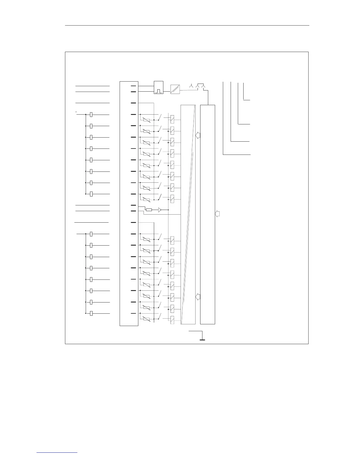
Data Memory and S5 Bus Control
Front StripConnection of
Process Signal
Lines
Example of connection designation
for an output:
Output 6 (6th bit);
0 to 7 possible
Address of output
byte (1st byte);
0 to 255 possible
Q = Output
2nd terminal L+ (not
specified in the ad-
dress)
Block Diagram of
Module Inputs
g = Green LED (status indicator)
F+/F-= Enable input
P0/M0 = Group of 8/load supply voltage (1st group)
P1/M1 = Group of 8/load supply voltage (2nd group)
L+/L-= Relay supply voltage (24 V DC)
1)
Changeover of enable mode with jumper X2: 1 - 2
Jumper inserted = Enable input active (factory setting)
Jumper open = Enable input inactive.
Digital Input/Output Modules
 Loading...

