EasyManua.ls Logo

Siemens S5-135U/155U - Page 416

Siemens S5-135U/155U
560 pages
To Next Page IconTo Next Page
To Previous Page IconTo Previous Page
Loading...
9-34
System Manual
C79000-G8576-C199-06
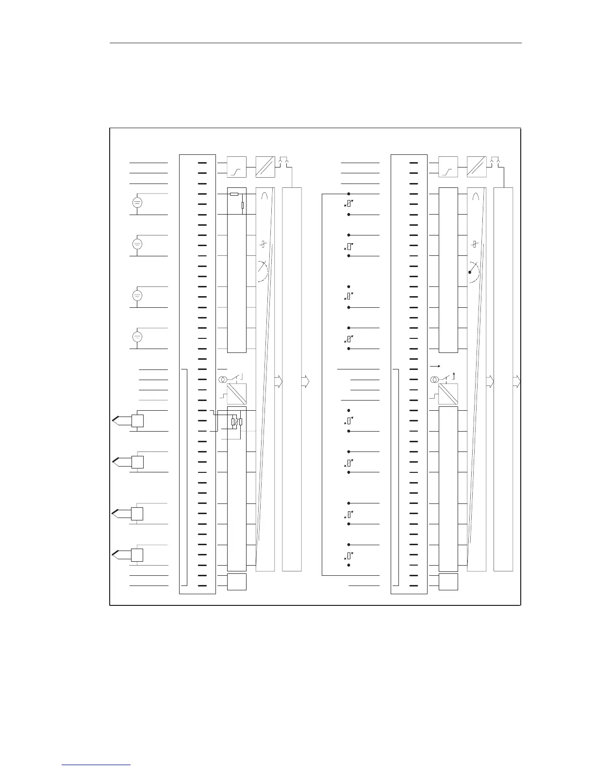
Voltage or current-input resistance thermometer or connection of two-wire
transducer
I
const.
1
2
3
4
6
8
10
13
15
17
19
21
22
23
25
27
29
31
34
36
38
40
41
42
F+
L+
F–
L–
Ch.0
Ch.1
Ch.2
Ch.3
Comp.–
Comp.+
Ch.4
Ch.5
Ch.6
Ch.7
Data Memory and S5 Bus Control
ADU
t
Range Card 2
Range Card 1
I
c+
c–
I
L–
I
trip
24
L+
3)
4)
#
Front Strip
Pin
L–
L–
L+
I
const.
Connection of
Process Signal
Lines
1
2
3
4
6
8
10
13
15
17
19
21
22
23
25
27
29
31
34
36
38
40
41
42
F+
L+
1)
F–
L–
Ch.0
1)
+
Ch.1
1)
+
Ch.2
1)
4)
+
Ch.3
Comp.–
Comp.+
I+
c
I–
c
T
T
T
T
1)
1)
1)
1)
+
+
2)Ch.4
+
+
+
2)Ch.5
2)Ch.6
2)Ch.7
ADU
t
Range Card 2
Range Card 1
6ES5 498–1AA51
I
trip
L+
3)
24
#
Front Strip
Pin
Connection of
Process Signal
Lines
Block Diagram
of the Modules
Block Diagram
of the Modules
Data Memory and S5 Bus Control
Figure 9-11 Front Connector Assignments
1) Observe
permissible
potential
difference
between
sensor
ground
and
reference
potential
of
modules
or
between
sensor
grounds.
2) Two-wire
transducer
3) Only
required
to
switch
off
the
tripping
current
without
broken
wire
detection;
0
V
at
L-.
4) Connect
L-
to
the
central
ground
point
(reference
potential).
Front Connector
Assignments
Analo
g
Input/Output Modules

Table of Contents

Related product manuals