4-11
System Manual
C79000-G8576-C199-06
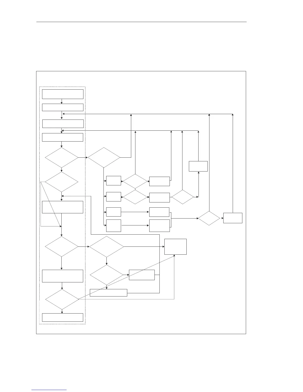
The following flowchart provides an overview of the sequence for startup
and validity check of a CC with CPU inserted and with no user program. For
the CPU 948, all steps relating to the memory submodule are skipped.
No
No
No
No
No
No
No
Connect power supply unit
Switch on supply voltage
CPU:
LED “BASP” on
LED “STOP” flashing fast
all others off
PS:
Correctly wired?
Voltage Present?
LED “Fan
Fault” on
LED
“Voltage
Low” on
Check load
voltage
connection
Check
Fan
CPU:
LED “STOP” on
LED “BASP” on
CPU:
LED ”BASP” on
LED “STOP” flashing fast
all others
off
Replace PS
Unit O.K.
Replace memory submodule
Reset CPU: Set to “Reset,”
switch from “STOP” to “RUN”
CPU:
LED “RUN” on,
LED “BASP” off
Memory
submodule:
correctly inserted?
Insert memory
submodule correctly
CPU general reset
PS:
LED “DC5V”
and “DC 24V” on, all
others off
Insert memory submodule in
CPU (not with the CPU 948)
CPU at “STOP”
Replace CPU
or
repeat startup
LED “MB
Low” on
LED “RB
Low” on
Check backup bty
and replace
if necessary
Replace
rechargeable
battery
Replace bty
compartment
Fault
corrected
No
No
No
No
Yes
Yes
Yes
Yes
Yes
Yes
Yes
Yes
Yes
Yes
Yes
Press
RESET
LED off
all others off
Press
RESET
LED off
Fault
corrected
Figure 4-5 Startup
Startup and
Validity Check
Central Controllers and Expansion Units Power Suppl
Unit
 Loading...

