EasyManuals Logo

Siemens SICAM A8000 Series User Manual

Siemens SICAM A8000 Series
82 pages
To Next Page IconTo Next Page
To Previous Page IconTo Previous Page
Page #41 background imageLoading...
Page #41 background image
Standard I/O Modules
SICAM A8000 Series, SICAM I/O Modules Unrestricted 41
DC8-012-2.06, Edition 09.2019
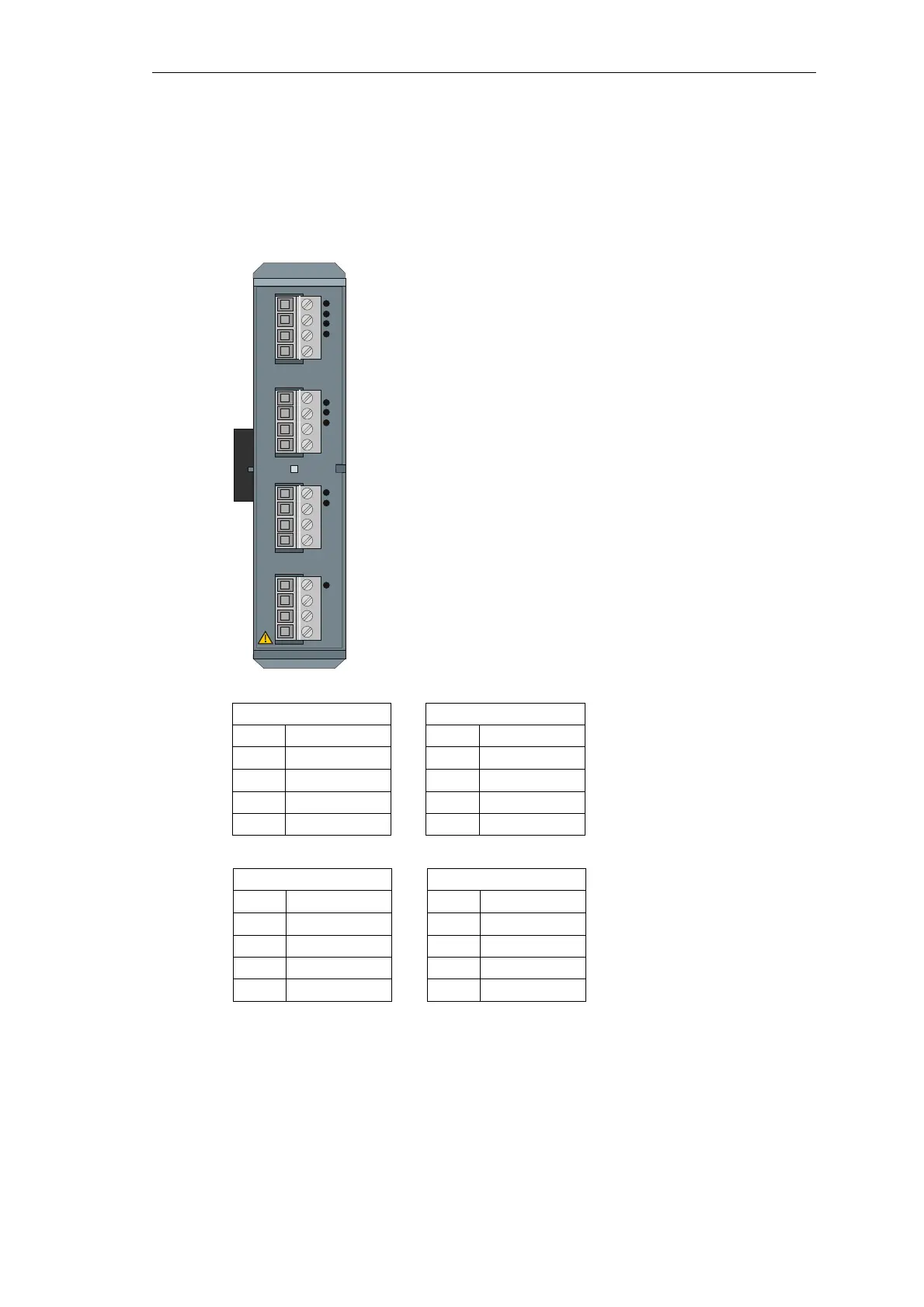
2.5.4 Pin Assignment and Display
The process signals must be connected to 4 pieces 4-pin screw terminals. The pin
assignment of the peripheral connectors is described in the following table.
X1 X2
Pin Signal Pin Signal
4 COM D01 4 COM D03
3 COM D00 3 COM D02
2 OUT D01 2 OUT D03
1 OUT D00 1 OUT D02
X3 X4
Pin Signal Pin Signal
4 COM D05 4 COM D07
3 COM D04 3 COM D06
2 OUT D05 2 OUT D07
1 OUT D04 1 OUT D06
OUT D00…OUT D07 binary outputs 0…7
COM D00…COM D07 common/outputs 0…7
RY readiness
RY
SICAM A8000 DO-8212
X4
X3
X2
X1
1
2
3
4
1
2
3
4
1
2
3
4
1
2
3
4

Table of Contents

Other manuals for Siemens SICAM A8000 Series

Questions and Answers:

Question and Answer IconNeed help?

Do you have a question about the Siemens SICAM A8000 Series and is the answer not in the manual?

Siemens SICAM A8000 Series Specifications

General IconGeneral
Modular DesignYes
Operating Temperature Range-40°C to +70°C
Communication InterfaceEthernet, RS485, RS232
Protection ClassIP20
Communication ProtocolsIEC 61850, DNP3, Modbus, IEC 60870-5-104
Power Supply24 V DC, 230 V AC
MountingDIN rail
Digital InputsUp to 32
Digital OutputsUp to 16
Input Voltage Range24 V DC to 230 V AC

Related product manuals