Standard I/O Modules
46 Unrestricted SICAM A8000 Series, SICAM I/O Modules
DC8-012-2.06, Edition 09.2019
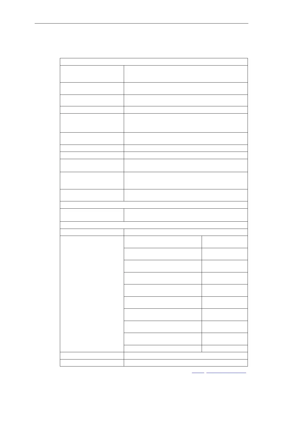
2.6.3 Technical Data
Analog Inputs
4 analog inputs
• 2 groups, 2 inputs each
• Galvanic insulation
•
Voltage between 2 inputs of a group max. DC 600 mV
Measuring ranges (resistance
measurement)
• 40 to 400 Ω (Pt100, Ni100)
• 400 to 4000 Ω (Pt1000)
Resolution
•
Ω
• 100 mΩ (Pt1000)
Noise rejection 16⅔ Hz, 50 Hz, 60 Hz
Conversion time Noise rejection for 50 Hz 200 ms
Noise rejection for 60 Hz 200 ms
Noise rejection for 16⅔ 500 ms
Accuracy
0.19 % 0 to +50 °C
0.4 % -40 to +70 °C
Reference current 250 μA
Connecting line impedance Sum of go-and-return line max. 300 Ω
Common mode rejection ratio 16⅔ Hz, 50 Hz, 60 Hz to 20 kHz > 100 dB
10 Hz to 1 MHz > 70 dB
Normal mode rejection ratio
16⅔ Hz > 106 dB
50 Hz > 98 dB
60 Hz > 91 dB
Input circuits
The circuits are operated by means of an internal voltage (constant-
current source)
Power Supply
Operating voltage DC 4.75 to 5.5 V max. 500 mW
The voltage is taken from the bus
Mechanics and Connectors
Terminals Removable screw terminals (grid size 5.08)
Connection data X1, X2
Locking torque
*)
(PHOENIX)
(FCI)
0.5 Nm to 0.6 Nm
0.36 Nm to 0.44 Nm
AWG
min. 22
max. 12
Conductor cross section solid
min. 0.33 mm²
max. 2.5 mm²
Conductor cross section stranded
min. 0.33 mm²
max. 2.5 mm²
Conductor cross section stranded with
ferrule without plastic sleeve
min. 0.33 mm²
max. 2.5 mm²
Conductor cross section stranded with
ferrule with plastic sleeve
min. 0.33 mm²
max. 2.5 mm²
2 wires stranded with ferrule without
plastic sleeve
min. 0.33 mm²
max. 1 mm²
2 wires stranded with TWIN ferrule with
plastic sleeve
min. 0.5 mm²
max. 1.31 mm²
Wire strip length
min. 6 mm
max. 7 mm
Length ferrule 10 mm
Dimensions 124 x 30 x 132 mm (L x W x H, dimensions w/o DIN rail)
Weight Approx. 241 g (incl. bus module 12 g)
*)
the respective manufacturer is imprinted at the terminal (see section 1.2.4.1, Screw Terminal Types)
 Loading...


