EasyManuals Logo

Siemens SICAM A8000 Series User Manual

Siemens SICAM A8000 Series
82 pages
To Next Page IconTo Next Page
To Previous Page IconTo Previous Page
Page #69 background imageLoading...
Page #69 background image
Standard I/O Modules
SICAM A8000 Series, SICAM I/O Modules Unrestricted 69
DC8-012-2.06, Edition 09.2019
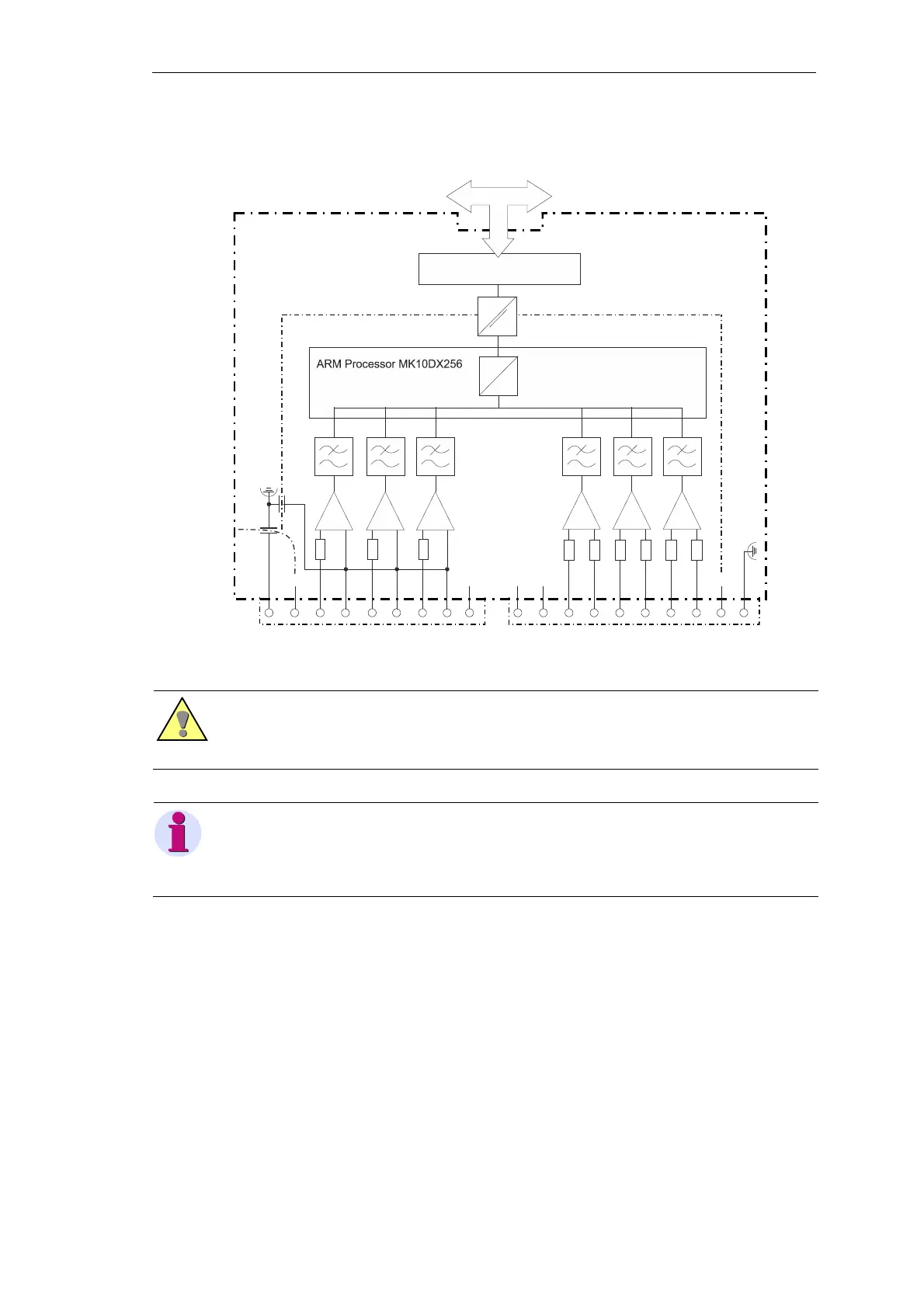
2.9.5 Block Diagram
Warning
The connectors X1 and X2 may be detached or attached in de
-energized state only!
The inputs of the connectors X1 and X2
must not be connected directly with a mains supply circuit!
Note
T
ake account of the direction of current flow when connecting the current measuring inputs. With inverse
connection, the measured values are inverted and receive a negative sign.
The
same applies correspondingly for the voltage measurement (direction and phase angle).
FE
X2
1
2
3
4
5
6
7
8
9
X1
1
2
3
4
5
6
7
8
9
10
DNC
N
N
N
DNC
DNC
I3-
DNC
DNC
I1+
I1-
I3+
A
D
U3
U2
U1
I2-/IN-
I2-/IN+
FE Shield
CC Shield
PIC Processor 18F45K22
reinforced insulation
internal BUS
AI-8511

Table of Contents

Other manuals for Siemens SICAM A8000 Series

Questions and Answers:

Question and Answer IconNeed help?

Do you have a question about the Siemens SICAM A8000 Series and is the answer not in the manual?

Siemens SICAM A8000 Series Specifications

General IconGeneral
Modular DesignYes
Operating Temperature Range-40°C to +70°C
Communication InterfaceEthernet, RS485, RS232
Protection ClassIP20
Communication ProtocolsIEC 61850, DNP3, Modbus, IEC 60870-5-104
Power Supply24 V DC, 230 V AC
MountingDIN rail
Digital InputsUp to 32
Digital OutputsUp to 16
Input Voltage Range24 V DC to 230 V AC

Related product manuals