EasyManuals Logo

Siemens SICAM A8000 Series User Manual

Siemens SICAM A8000 Series
82 pages
To Next Page IconTo Next Page
To Previous Page IconTo Previous Page
Page #68 background imageLoading...
Page #68 background image
Standard I/O Modules
68 Unrestricted SICAM A8000 Series, SICAM I/O Modules
DC8-012-2.06, Edition 09.2019
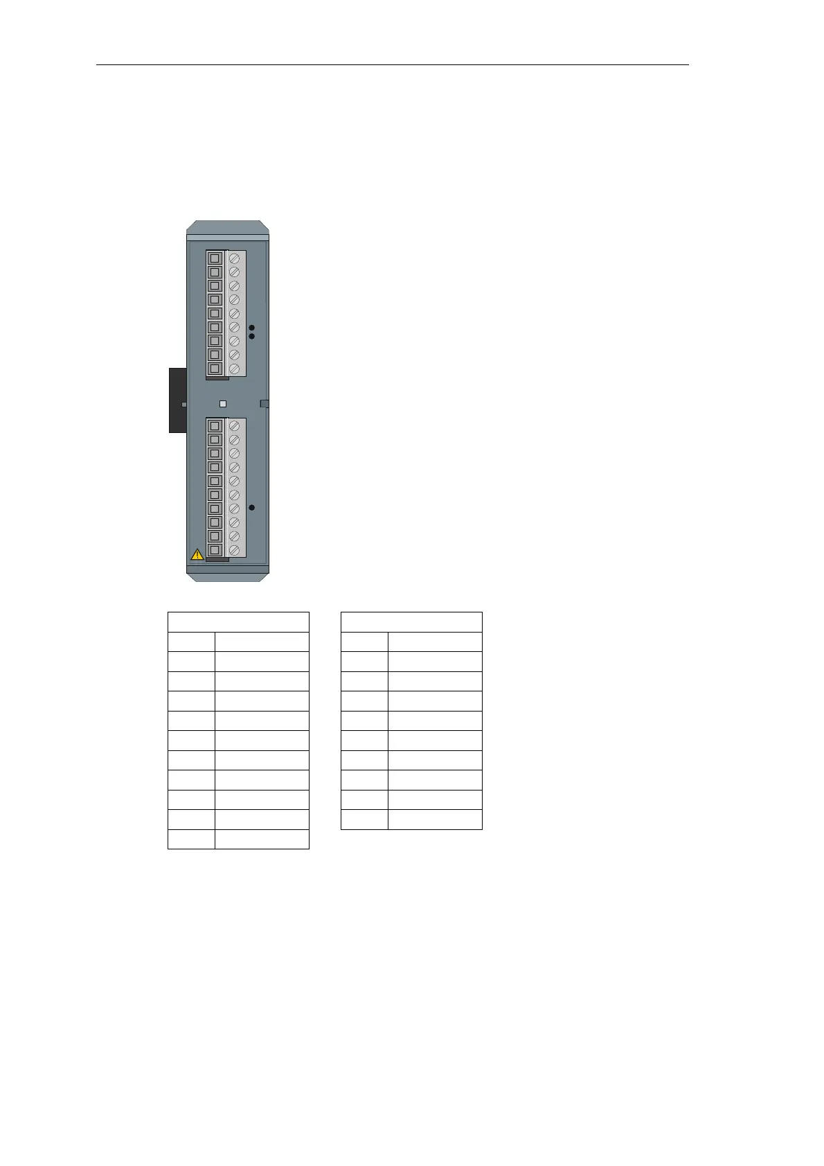
2.9.4 Pin Assignment and Display
The process signals must be connected to 2 screw terminals. The pin assignment of the
peripheral connectors is described in the following table.
X1 X2
Pin Signal Pin Signal
10 DNC 9 CC shield
9 DNC 8 DNC
8 I1+ 7 U1
7 I1- 6 N
6 I2+/IN+ 5 U2
5 I2-/IN- 4 N
4 I3+ 3 U3
3 I3- 2 N
2 DNC 1 DNC
1 FE shield
RY readiness
I1+/-…I3+/- measuring current inputs
IN+/- (sensitive) ground current
U1/N…U3/N measuring voltage inputs
FE functional earth
CC capacitive coupled to protective earth
DNC do not connect
RY
SICAM A8000
AI-8511
X2
X1
1
2
3
4
5
6
7
8
9
10
1
2
3
4
5
6
7
8
9

Table of Contents

Other manuals for Siemens SICAM A8000 Series

Questions and Answers:

Question and Answer IconNeed help?

Do you have a question about the Siemens SICAM A8000 Series and is the answer not in the manual?

Siemens SICAM A8000 Series Specifications

General IconGeneral
Modular DesignYes
Operating Temperature Range-40°C to +70°C
Communication InterfaceEthernet, RS485, RS232
Protection ClassIP20
Communication ProtocolsIEC 61850, DNP3, Modbus, IEC 60870-5-104
Power Supply24 V DC, 230 V AC
MountingDIN rail
Digital InputsUp to 32
Digital OutputsUp to 16
Input Voltage Range24 V DC to 230 V AC

Related product manuals