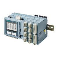
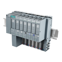
Standard I/O Modules
SICAM A8000 Series, SICAM I/O Modules Unrestricted 71
DC8-012-2.06, Edition 09.2019
2.9.6.2 Ground Fault Indicator
The current input I2/IN is connected with the LoPo sum current measuring sensor.
In this configuration, the module functions as non-directional ground fault indicator.
2.9.6.3 Fault Detector
The current inputs I1, I2/IN, I3 are connected through the adaptor module CM-8820 with the
corresponding LoPo measuring sensors. Additionally, the voltage inputs U1, U2, U3 are
connected
• through LoPo voltage transformers of 3.25 V/√3 with the medium-voltage network
In this configuration, fault information with directional indication is output. Thereby, also all the
measured and calculated measurands are provided.
P1
P2
S1 S2
225 mV
N
L3
L2
L1
AI-8511
X2
1
2
3
4
5
6
7
8
9
X1
1
2
3
4
5
6
7
8
9
10
DNC
I3-
I3+
I1-
I1+
DNC
DNC
DNC
N
N
N
DNC
I2-/IN+
I2-/IN-
U3
U2
U1
FE Shield
CC Shield

 Loading...


