Wiring
4.2 Block diagram
F-TM ServoDrive
22 Equipment Manual, 02/2020, A5E47579503-AA
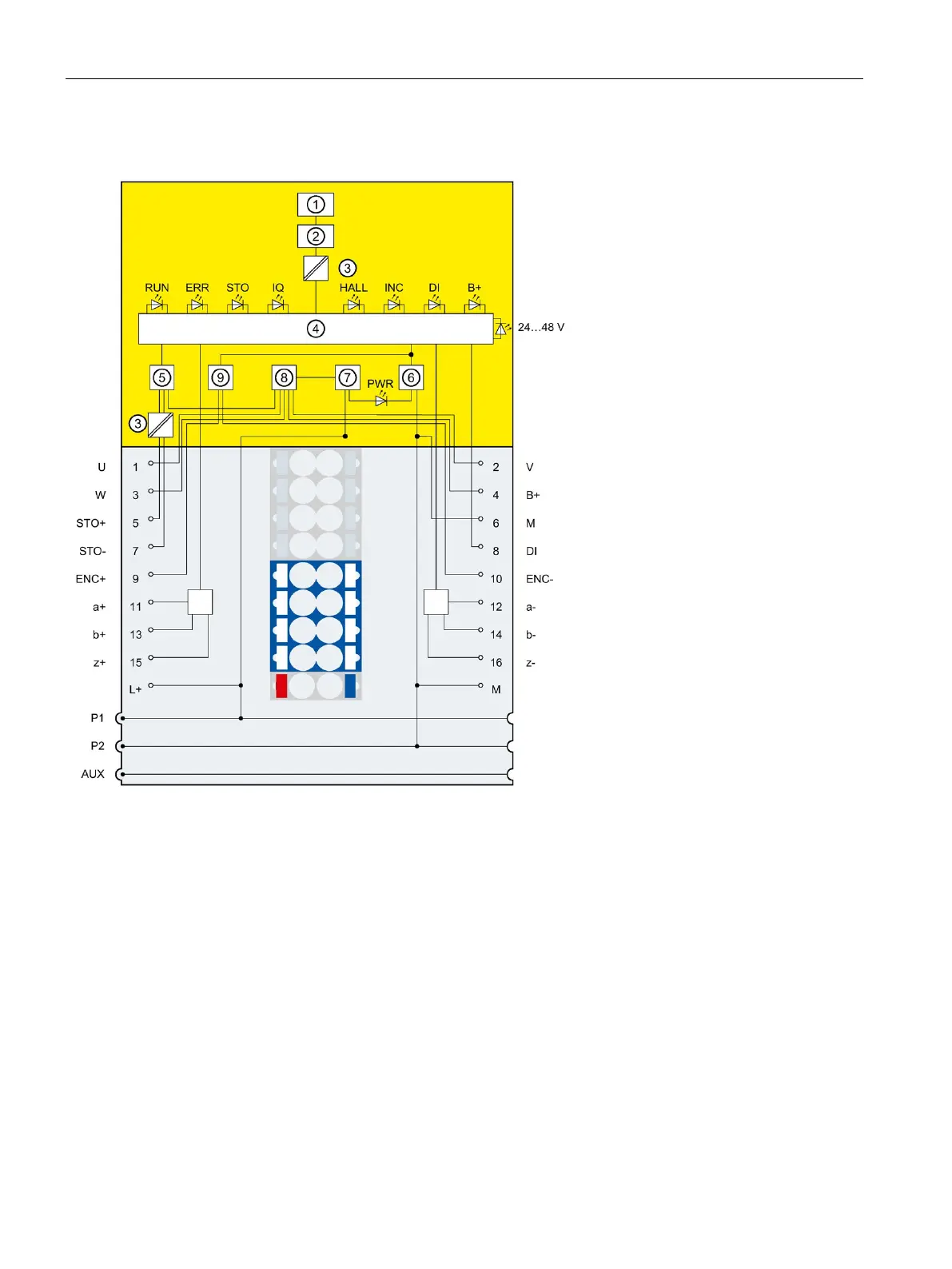
Schematic circuit diagram
Backplane bus interface module of the technol-
ogy controller
Connection of braking resistor
Safe Torque Off circuitry
Negative connection, e.g. for braking resistor
Reverse polarity protection
Power supply encoder, negative connection
Differential encoder signal a+
Differential encoder signal a-
Differential encoder signal b+
Differential encoder signal b-
Differential encoder signal z+
Differential encoder signal z-
Figure 4-1 Schematic circuit diagram
 Loading...


