Wiring
4.2 Block diagram
F-TM ServoDrive
Equipment Manual, 02/2020, A5E47579503-AA
23
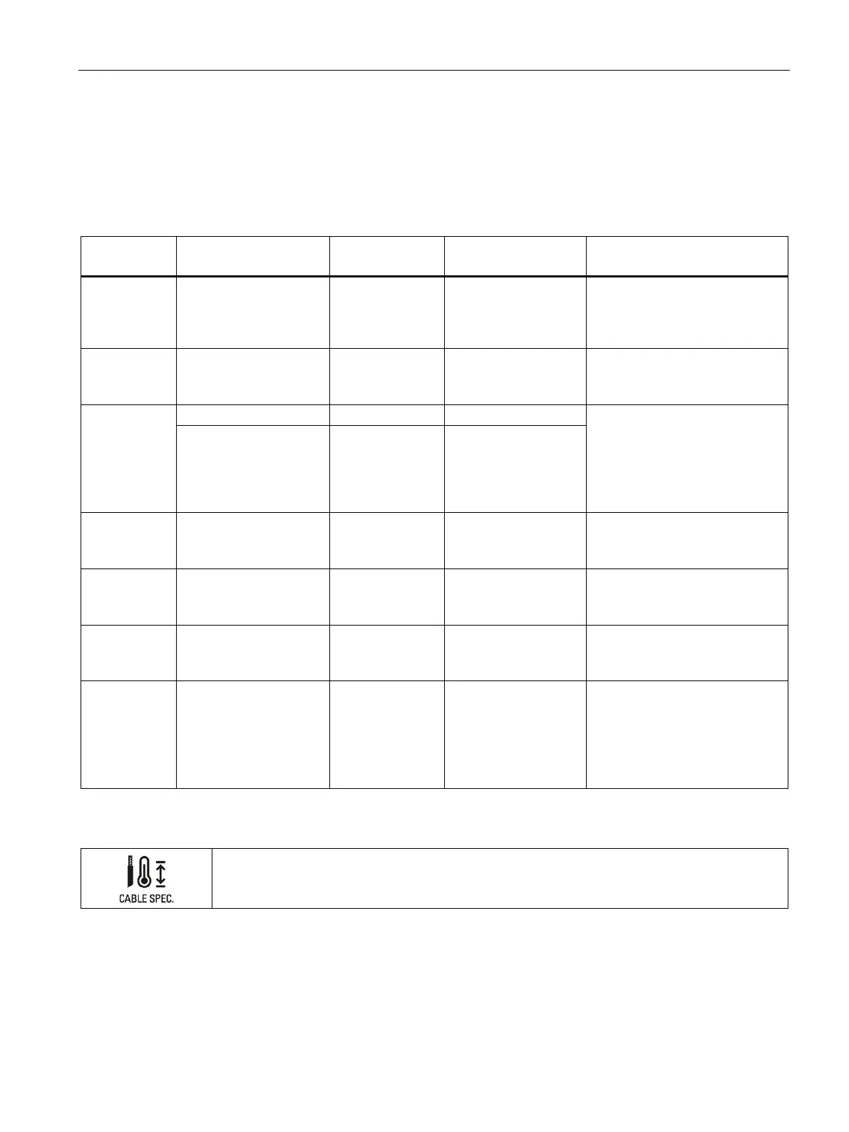
Cable lengths and cable types
If you do not use an "all-in-one" plug-in cable, the following cable lengths and cable types
are permitted for the interfaces:
Table 4- 1 Wiring rules for the interfaces
ENC+/ENC- Incremental encoder
signals and supply
10 m Shielded
For differential wiring,
one twisted pair per
Solid and stranded supply cable:
AWG*: 22 to 16 or
0.34 mm
2
to 1.5 mm
2
U/V/W Motor phases 10 m Shielded Solid and stranded supply cable:
AWG*: 20 to 14 or
2
2
DI, M
Solid and stranded supply cable:
AWG*: 22 to 16 or
0.34 mm
2
to 1.5 mm
2
For through-wiring for maximum
permissible terminal currents, use
2
Ground 10 m -
L+/M Power supply, power
unit
10 m - Solid and stranded supply cable:
AWG*: 20 to 14 or
2
2
B+ Connection of external
braking resistor
2 m ≥ 0.5 m shielded Solid and stranded supply cable:
AWG*: 18 to 16 or
2
2
a, b, z Encoder connectors 10 m Shielded Solid and stranded supply cable:
AWG*: 18 to 14 or
2
2
STO Safe Torque Off 10 m - Solid and stranded supply cable:
AWG*: 20 to 16 or
0.5 mm
2
to 1.5 mm
2
For through-wiring for maximum
permissible terminal currents, use
2
Note that connected mains lines must be designed according to the expected minimum and maxi-
mum ambient temperature.
 Loading...


