EasyManuals Logo

Siemens simatic et200sp Function Manual

Siemens simatic et200sp
58 pages
To Next Page IconTo Next Page
To Previous Page IconTo Previous Page
Page #39 background imageLoading...
Page #39 background image
Circuit diagram example
4.4 TIA Portal configuration
Safety engineering with AS‑Interface in the SIMATIC ET 200SP, including typical circuit diagram
Function Manual, 08/2020, A5E44991382002A/RS-AB/002
39
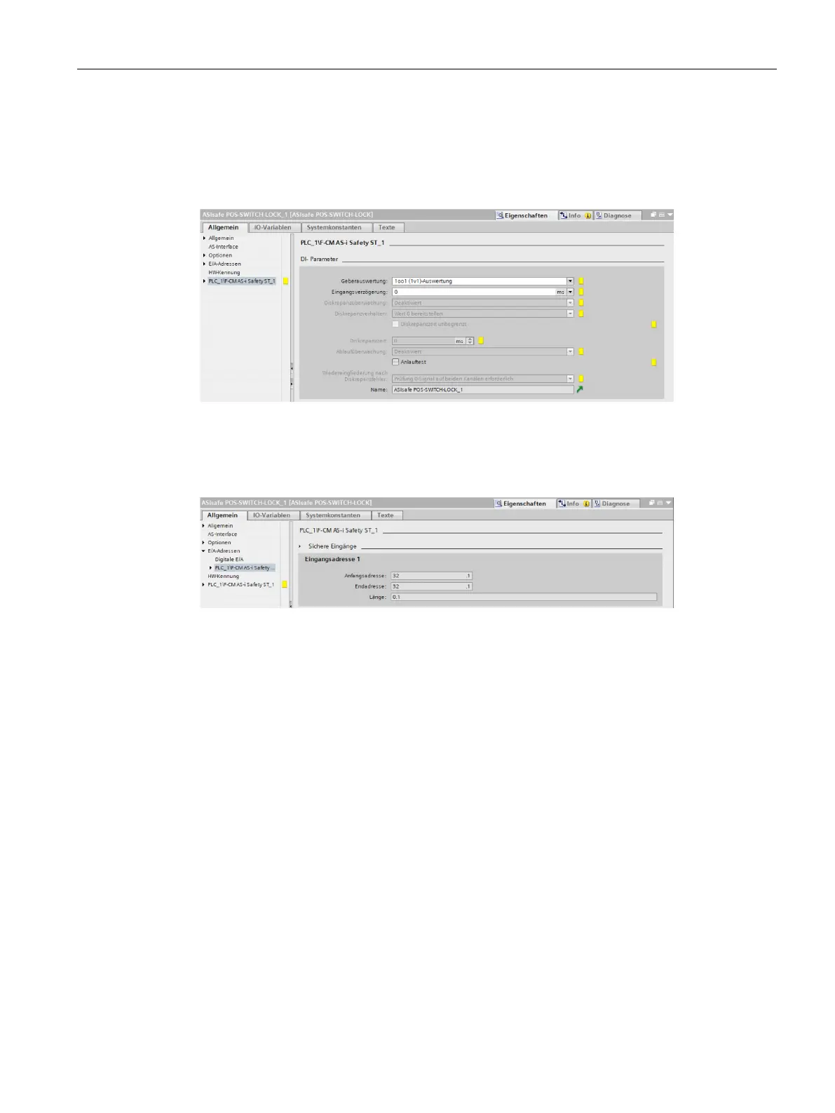
The safe monitoring of the position switch is then configured as follows. The explanation of
the individual parameters can be found in Section 4.4.5 (Page 36). A 1oo1 evaluation is
selected to monitor the position switch because the switch used (version 3SF13 ... 1BA4) is
already monitored for discrepancy (see Section 4.2.3 (Page 25)).
Figure 4-12 Configuration of the position switch
The position signal of the position switch is transferred to the safety program as a safe input
bit. The address of the safe input is shown in the following figure (I32.1 in this example).
Figure 4-13 Address for reading out the position of the position switch

Other manuals for Siemens simatic et200sp

Questions and Answers:

Question and Answer IconNeed help?

Do you have a question about the Siemens simatic et200sp and is the answer not in the manual?

Siemens simatic et200sp Specifications

General IconGeneral
CategoryI/O Systems
Power Supply24 V DC
Protection RatingIP20
Number of ModulesUp to 64 modules
MountingDIN Rail
Communication ProtocolsPROFINET, PROFIBUS
Storage Temperature-40 °C to +70 °C
Digital InputsYes (depending on module)
Digital OutputsYes (depending on module)
Analog InputsYes (depending on module)
Analog OutputsYes (depending on module)
ModularityModular
Relative Humidity5 to 95% (non-condensing)
WeightVaries by configuration
System TypeDistributed I/O

Related product manuals