EasyManuals Logo

Siemens simatic et200sp Function Manual

Siemens simatic et200sp
58 pages
To Next Page IconTo Next Page
To Previous Page IconTo Previous Page
Page #41 background imageLoading...
Page #41 background image
Circuit diagram example
4.4 TIA Portal configuration
Safety engineering with AS‑Interface in the SIMATIC ET 200SP, including typical circuit diagram
Function Manual, 08/2020, A5E44991382002A/RS-AB/002
41
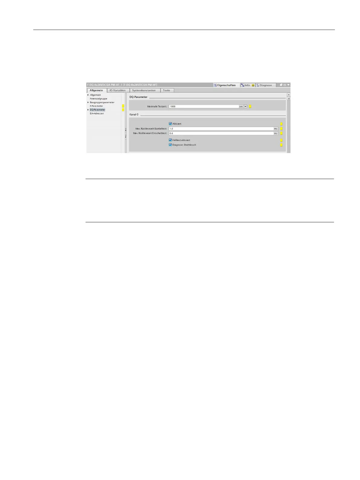
Finally, the F-DQ module is configured to control the redundant contactors. Here again, the
F parameters remain unchanged (default setting). The setting of the safe monitoring can be
taken from the following figure.
Figure 4-16 Configuration of the F-DQ module
Note
Unused channels, such as channels 1 to 3 of the F
-DQ module, should be deactivated for
reasons of clarity and improved performance. For this purpose, the check is removed from
"Activated" for the
corresponding channels. For the F-CM AS-i Safety ST module, the user
must activate the input channels required for the configured AS-i slaves.

Other manuals for Siemens simatic et200sp

Questions and Answers:

Question and Answer IconNeed help?

Do you have a question about the Siemens simatic et200sp and is the answer not in the manual?

Siemens simatic et200sp Specifications

General IconGeneral
CategoryI/O Systems
Power Supply24 V DC
Protection RatingIP20
Number of ModulesUp to 64 modules
MountingDIN Rail
Communication ProtocolsPROFINET, PROFIBUS
Storage Temperature-40 °C to +70 °C
Digital InputsYes (depending on module)
Digital OutputsYes (depending on module)
Analog InputsYes (depending on module)
Analog OutputsYes (depending on module)
ModularityModular
Relative Humidity5 to 95% (non-condensing)
WeightVaries by configuration
System TypeDistributed I/O

Related product manuals