8
8-4
FM 351 Positioning Function Module
EWA 4NEB 720 6001-02
8.2 Machine Data for the Drive
The machine data for the drive describes:
How the FM 351 can control a drive (power controller) using its outputs.
How a target approach is executed and monitored.
All data for the Drive input range can be found in the following table:
Table 8-2 Drive Data
Machine Data and
Assignment
Description
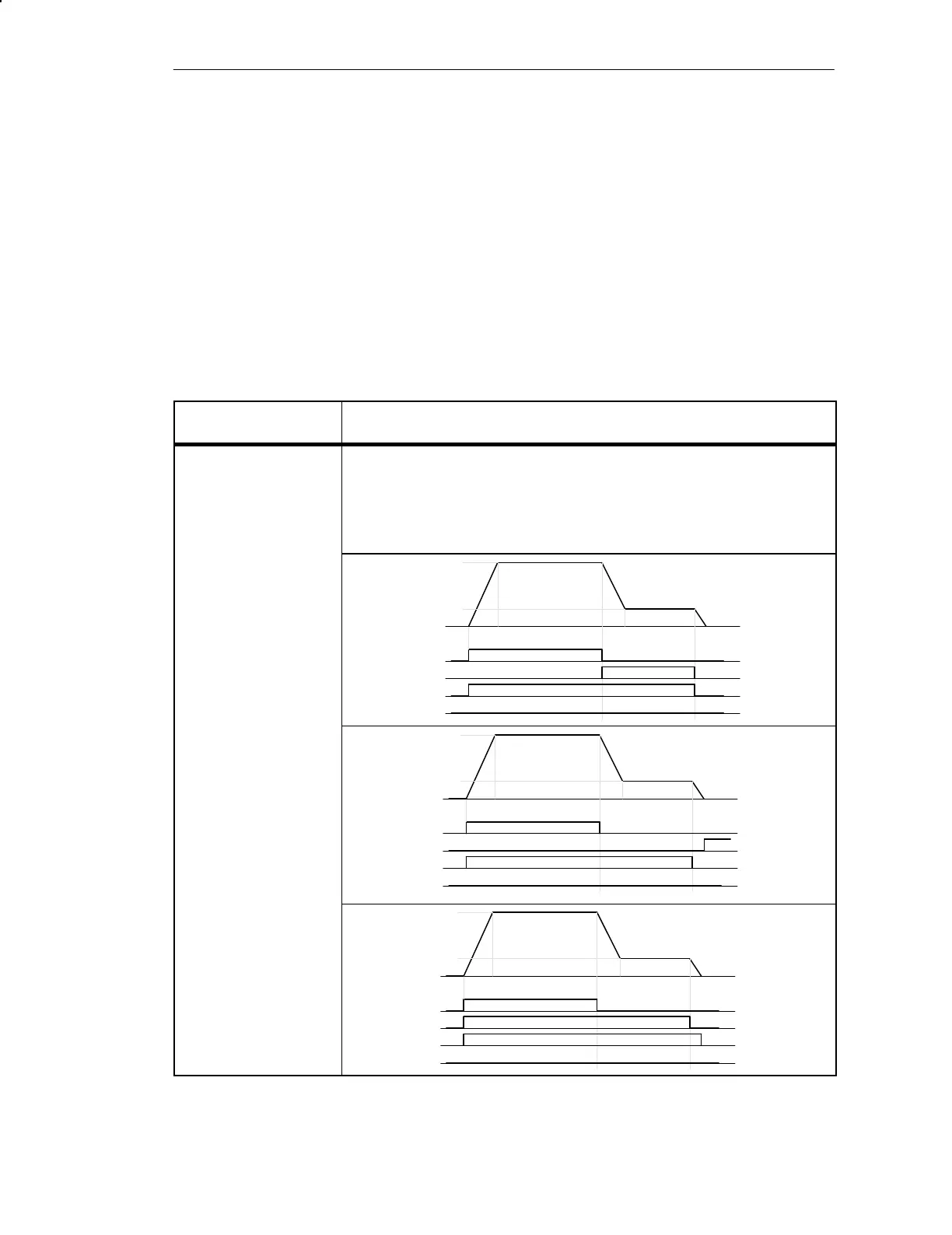
Control type
1
2
3
4
The control type describes how the four digital outputs per channel operate a con-
nected motor via the power controller.
Channel 1 is displayed in each of the following diagrams.
Control type 1
1Q0/2Q0: Rapid speed
1Q1/2Q1: Creep speed
1Q2/2Q2: Positive ap-
proach
1Q3/2Q3: Negative ap-
proach
v
rapid
v
creep
1Q0
1Q1
1Q2
1Q3
Control type 2
1Q0/2Q0: Rapid speed/
creep speed
1Q1/2Q1: Position
reached
1Q2/2Q2: Positive ap-
proach
1Q3/2Q3: Negative ap-
proach
v
rapid
v
creep
1Q0
1Q1
1Q2
1Q3
Control type 3
1Q0/2Q0: Rapid speed
1Q1/2Q1: Creep speed
1Q2/2Q2: Positive ap-
proach
1Q3/2Q3: Negative ap-
proach
v
rapid
v
creep
1Q0
1Q1
1Q2
1Q3
Definition
Data List
Machine Data and Increments

 Loading...


