4
4-4
FM 351 Positioning Function Module
EWA 4NEB 720 6001-02
4.1 Wiring the Power Controller
The power controller is connected to the digital outputs on the FM 351. The
motor is controlled by the power controller.
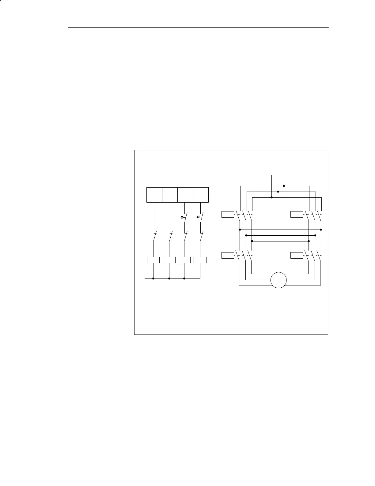
The power controller may for example consist of a simple contactor circuit.
In Figure 4-3 you can see the control and load circuits of a power controller.
The functions of the digital outputs correspond to Control Mode 1.
Load circuitControl circuit
1Q0
1Q1
1Q2
1Q3
Digital outputs on FM 351
M
K3
K4
K2
K1
K1
K2
K4
K3
K1 = Clockwise rotation
K2 = Counterclockwise rotation
K3 = Rapid speed
K4 = Creep speed
E1
E2
E1 = Limit switch, left
E2 = Limit switch, right
K1
K3
K2
K4
M
Pole-changing motor
L1 L2 L3
Figure 4-3 Contactor Circuit
Power Controller
Contactor Circuit
Wiring the FM 351

 Loading...


