4
4-6
FM 351 Positioning Function Module
EWA 4NEB 720 6001-02
4.2 Description of the Encoder Interface
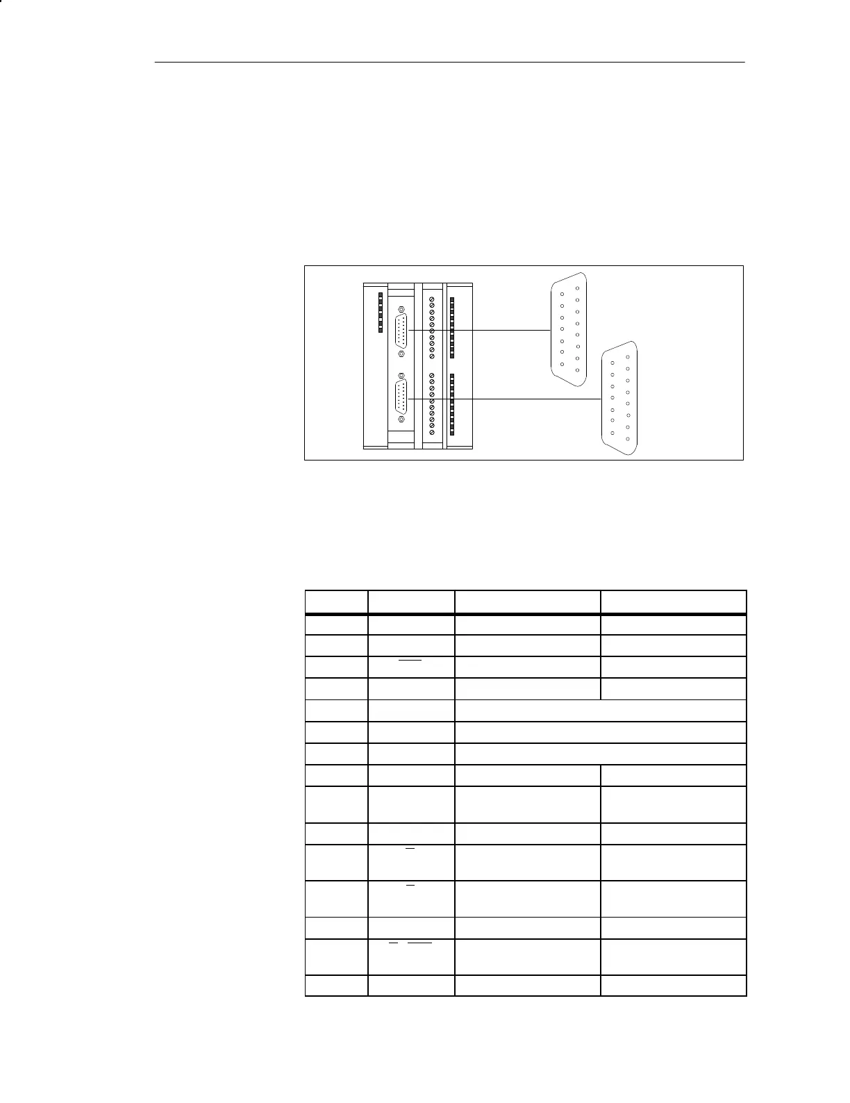
The mounting position and the designation of the sockets on the module are
shown in Figure 4-4. Incremental or absolute encoders (SSI) can be con-
nected to the two subminiature Cannon sockets.
FM 351
ENCODER X3
channel 2
1
15
8
9
1
15
8
9
ENCODER X2
channel 1
Figure 4-4 Position of the Subminiature Cannon Sockets X2 and X3
Table 4-1 shows the assignment of the 15-pin subminiature Cannon sockets:
Table 4-1 Assignment of the 15-Pin Subminiature Cannon Sockets X2 and X3
Pin Name Incremental Encoder Absolute Encoder
1 A* Encoder signal A (24 V) ---
2 CLS --- SSI shift clock
3 CLS --- SSI shift clock inverse
4 B* Encoder signal B (24 V) ---
5 24 VDC Encoder supply 24 V
6 5.2 VDC Encoder supply 5.2 V
7 M Ground
8 N* Zero mark signal (24 V) ---
9 RE Current sourcing/sinking
(See Chap. B.3)
---
10 N Zero mark signal (5 V) ---
11 N Zero mark signal inverse
(5 V)
---
12 B Encoder signal B inverse
(5 V)
---
13 B Encoder signal B (5 V) ---
14 A / DAT Encoder signal A inverse
(5 V)
SSI data inverse
15 A /DAT Encoder signal A (5 V) SSI data
Position of the
Subminiature Can-
non Sockets
Assignment of the
Sockets X2 and X3
Wiring the FM 351

 Loading...


