Description of Functions
9-74
FM 353 Stepper Drive Positioning Module
6ES7 353-1AH01-8BG0
Note
When using this signal, the signal “Controller ready” can be processed only by way
of the D Sub connector X2 (Signal Ready1_N)!
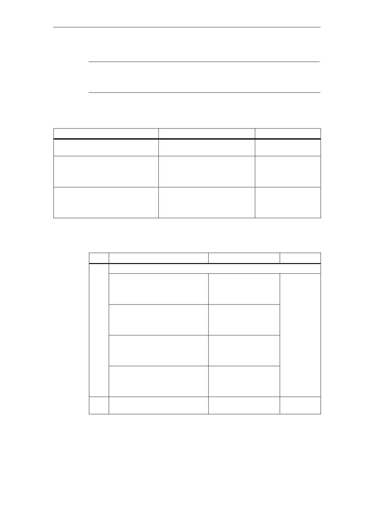
The following cases must be distinguished:
Technical implementation Signal shape Parameter definition
Signal encoder on the motor axis
(e.g. initiator)
Active phase over several motor in-
crements, one time per revolution
“Zero pulse external”
Cyclical signal generated by the stepper
drive one time per motor revolution (e.g.
zero trace of a motor-integrated incre-
mental encoder)
Active phase over one motor incre-
ment, one time per revolution
“Current-sourcing pat-
tern external” and
MD38=0
Cyclical one-time signal in current-
sourcing pattern from stepper drive
Active phase in current-sourcing
pattern zero of the stepper drive, n-
times per revolution (n = current-
sourcing pattern number)
“Current-sourcing pat-
tern external” and
MD38= MD13/n
The following table shows you the available machine data for parameterizing the
function.
MD Designation Value/Meaning
37 Special control signals
37.24 Current-sourcing pattern zero active 0:Current-sourcing pattern
zero not used
1:Current-sourcing pattern
zero used
Input signal
37.25 Current-sourcing pattern zero in-
verted
0:Current-sourcing pattern
zero high active
1:Current-sourcing pattern
zero low active
37.26 Zero pulse external active 0:Zero pulse external not
used
1:Zero pulse external
used
37.27 Zero pulse external inverted 0:Zero pulse external high
active
1:Zero pulse external low
active
38 No. of increments/current-sourcing
pattern cycle
2)
0...400
1)
1) Compare documentation from stepper drive manufacturer.
2) See Section 5.3.1, Dependencies

 Loading...


