Defining Parameters
5-20
FM 353 Stepper Drive Positioning Module
6ES7 353-1AH01-8BG0
5.3.2 Increments
DB structure
Table 5-5 gives you a general view of the structure of the “Increments” data block
(DB-SM).
Table 5-5 DB structure − increments
Byte
Variable type Value Significance of the variables Comment
DB header
0 WORD Rack slot Module address
2 WORD DB No. ( 1000) As in DB header
4 DWORD Reserved
8 WORD Error No. (from FM) With HMI services
10 WORD 1 Channel number
12 2 STRING SM DB identifier/type 2 ASCII characters
16 DWORD 353 Module identifier FM 353
20 4 CHAR 0 Version number/block number (DB structure)
24 DWORD 1 − 3 Measurement-system grid per MD7 Unit of measurement
28 WORD 0/1 Parameter (DB) backup Job via HMI
30 WORD Reserved
32 DWORD 0 − 10
9
Increment 1
36 DWORD 0 − 10
9
Increment 2 to increment 100 see Section 9.2.4
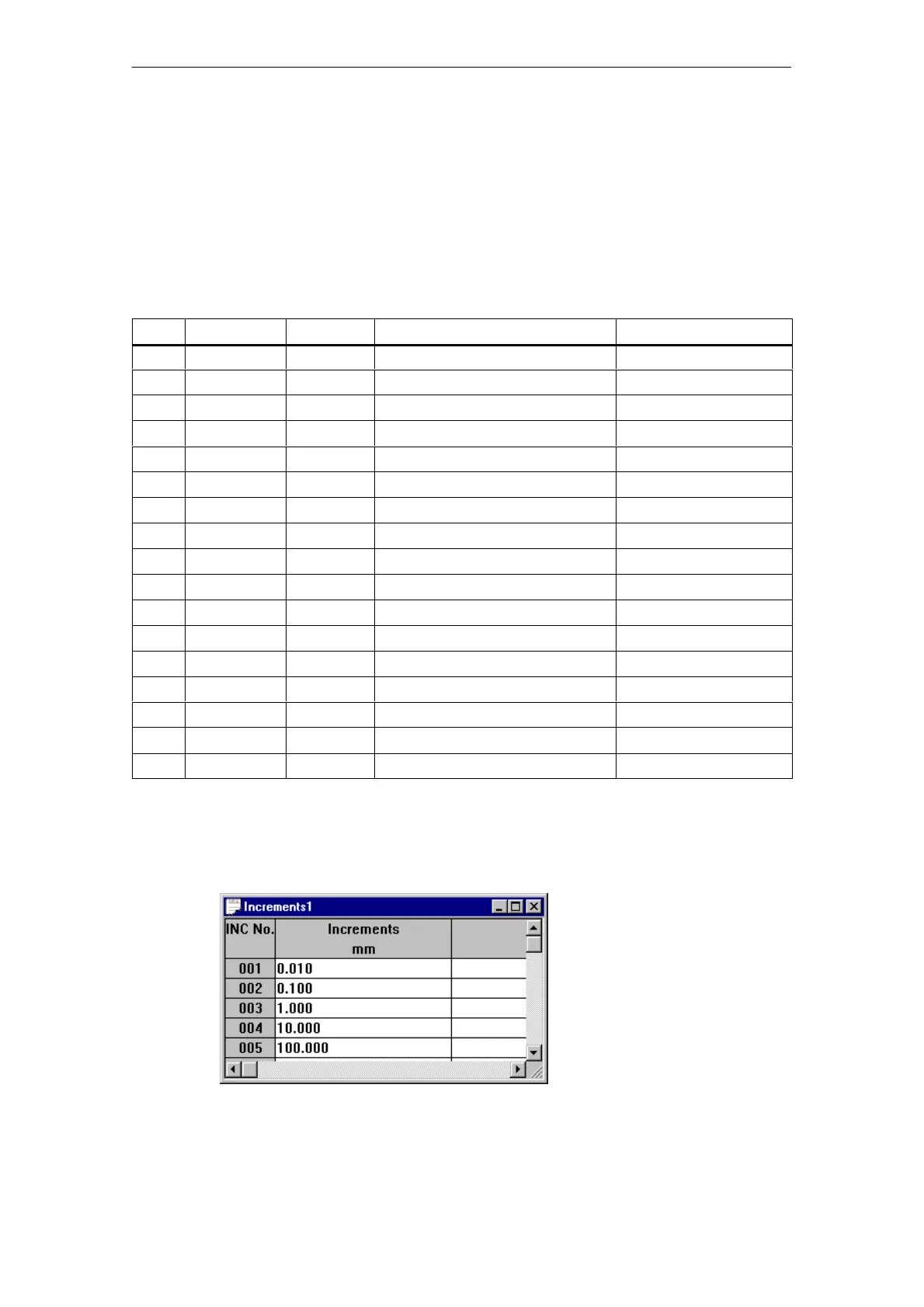
Input of values
Values are input in the increments menu of the “Parameterize FM 353” parameter-
ization tool.
Fig. 5-6 Entering values for incremental dimensions

 Loading...


