Defining Parameters
5-19
FM 353 Stepper Drive Positioning Module
6ES7 353-1AH01-8BG0
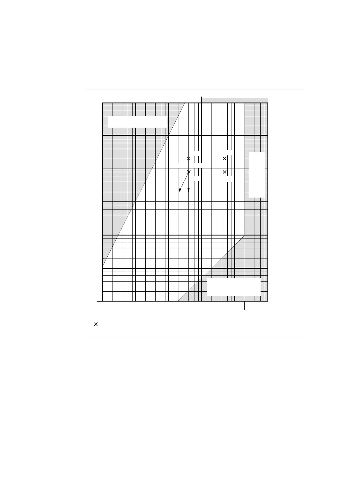
“Working range of frequency generator”
You can use the following diagram to check that the combination of parameters
selected in machine data MD39 to MD45 lie within the working range of the fre-
quency generator (white area).
f
max
[Hz]
f
ss
[Hz]
100 00010 0001 000
1 00010010 20 40
10 20 40 100 Hz/s 10 kHz/s 100 kHz/s1 kHz/s 1 MHz/s 10 MHz/s
Acceleration too great
with reference to f
ss
Max. frequency
absolute too high
t
over
df/dt
10 000
500
200 000
P1
P2
P4
P3
Working points of the frequency generator in the direction of shift of e.g. Px by the
acceleration override function (a
over
) and time override (t
over
).
a
over
Acceleration too low
with reference to
f
max
Fig. 5-5 Working range, frequency generator
Machine data values range:
Start/Stop frequency f
ss
: (MD39) 10 Hz − 10 kHz
Maximum frequency f
max
: (MD41) 500 Hz − 200 kHz
Frequency rise df/dt: (MD42 − 45) 10 Hz/s − 10 MHz/s
Condition: The intersections of the lines df/dt and f
ss
d df/dt
with f
max
must be within the white area!
Example: MD39 = 4 kHz, MD41 = 50 kHz
MD42, 44 = 200 kHz/s P1/P2
MD43, 45 = 80 kHz/s P3/P4
 Loading...


