Technical information
7.5 Technical specifications
IFP Basic
72 Operating Instructions, 06/2023, A5E46178354 - AD
2
: Atmospheric pressure and air density increases with decreasing altitude. Therefore
utilization of the derating factor for 0 m to 2000 m for altitudes below sea level is considered
conservative. The altitude of operation is maximum 2000 m for Hazardous Locations
applications.
Note the information in section "Notes about usage (Page 15)" .
7.5.2.3 Electromagnetic compatibility
Pulse-shaped interference
The following table shows the electromagnetic compatibility of modules with regard to pulse-
shaped interference. This requires the device to meet the specifications and directives for
electrical installation.
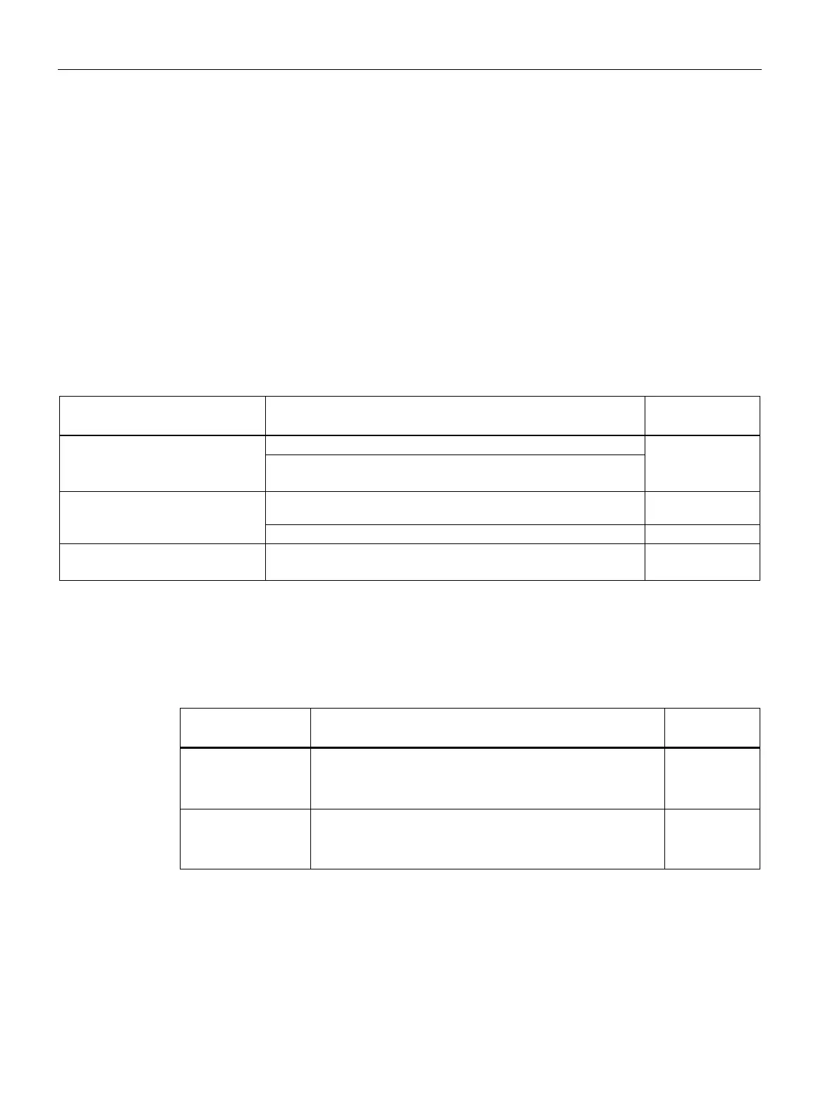
Pulse-shaped interference Tested with Performance
in accordance with IEC 61000-4-2
Contact discharge: ± 4 kV (IFP Basic)
Contact discharge: ± 6 kV (IFP Basic C)
(high-speed transient interference)
in accordance with IEC 61000-4-4
± 1 kV signal cable, < 30 m
IEC 61000-4-5
± 1 kV line-to-line of DC port
± 2 kV line-to-earth of DC port
Sinusoidal interference
The following table shows the EMC behavior of the modules with respect to sinusoidal
interference. This requires the HMI device to meet the specifications and directives for
electrical installation.
Sinusoidal interfer-
Test values Degree of
tromagnetic fields)
according to
80% amplitude modulation at 1 kHz
with 10 V/m in the range of 80 MHz to 1 GHz
with 3 V/m in the range 1.4 GHz to 2 GHz
with 3 V/m in the range 2 GHz to 6 GHz
lines and line shields
according IEC 61000-
Test voltage 10 V, with 80% amplitude modulation of 1 kHz
in the 150 kHz to 80 MHz range
Emission of radio interference
The following table shows the emitted interference from electromagnetic fields according to
EN 61000-6-4, measured at a distance of 10 m.