(QFRGHU
5HGXQGDQWLQSXWPRGXOH
(70
[,0
6+
352),%86'3
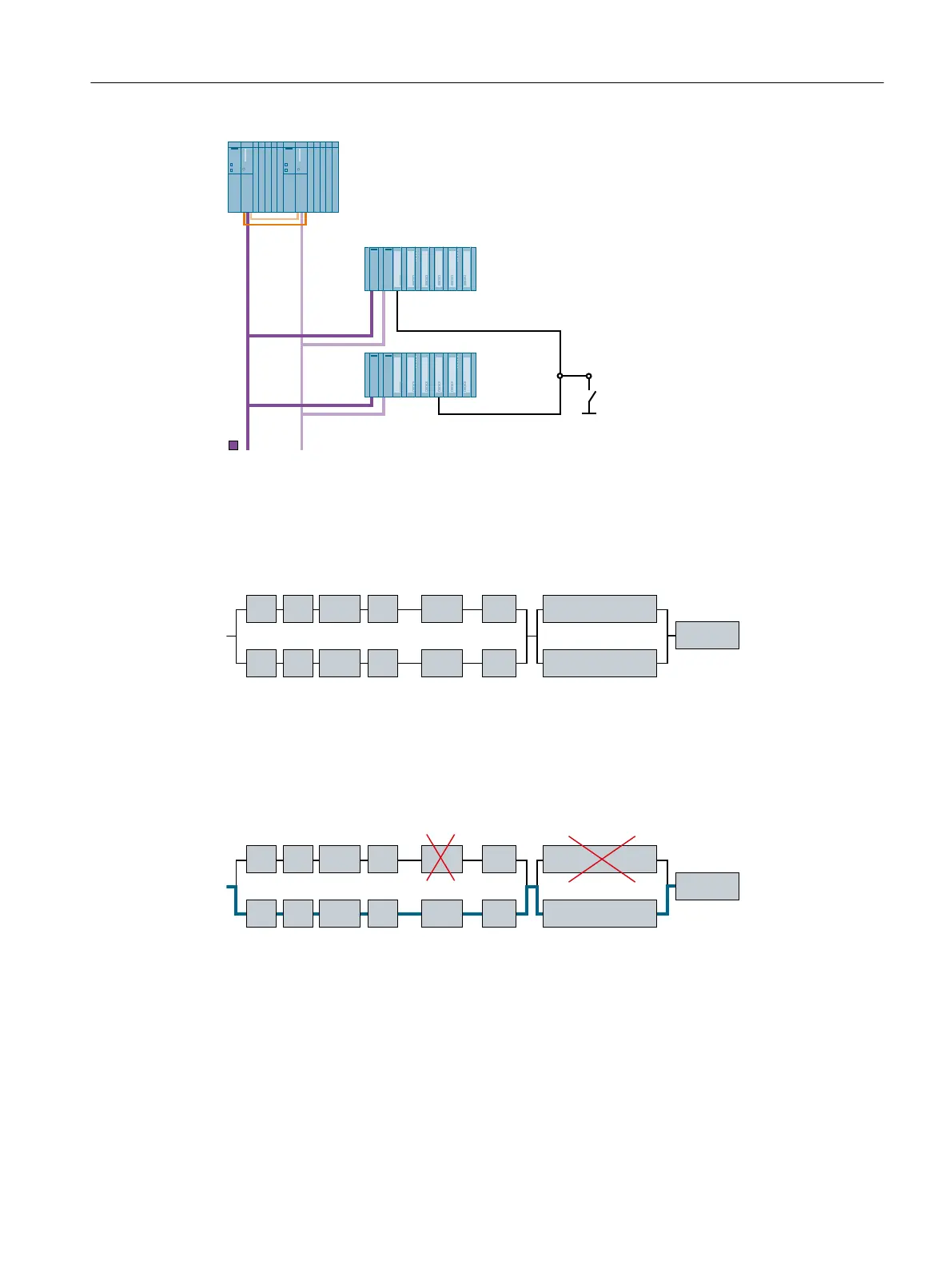
Availability
The block diagram shows an example configuration with ET 200M without a fault.
(QFRGHU
60LQ(70
,,
60LQ(70
,
%XV
+V\VWHP
%XV
&38,0
&38
&3
&3,0
&3
&336
36
(70
If a fault occurs in a maximum of one signal path per redundancy node (e.g. bus line
(bus = PROFIBUS DP) in the first redundancy node and an input module (SM) in the second
redundancy node), the overall system remains operable. The connected device continues to
supply data to the central device, which remains available. If any other component in the
redundancy chain fails, however, the complete system will fail.
(QFRGHU
60LQ(70
,,
60LQ(70
,
%XV
+V\VWHP
%XV
&38,0
&38
&3
&3,0
&3
&336
36
(70
High availability solutions in PCS 7
4.1 Solutions for the I/O
High Availability Process Control Systems (V9.0)
Function Manual, 05/2017, A5E39221836-AA 39
 Loading...


