System overview
3.5 Design
PN/M-Bus LINK
14 Operating Instructions, 03/2018, A5E44260928-AA
Design
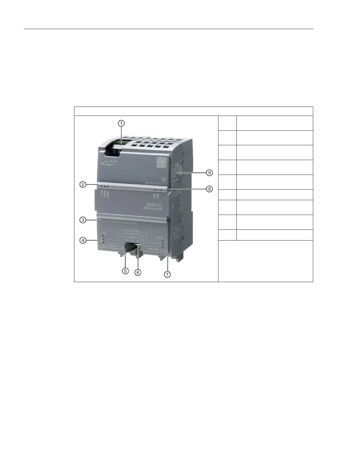
PN/M-BUS LINK setup
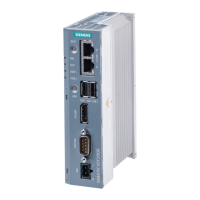
The following figure shows the arrangement of the connection and display elements on
PN/M-Bus LINK. The figure shows the device without a top and bottom enclosure cover.
①
24 V DC + functional
Status LEDs device operating
state + PROFINET
③
MAC address that the device
④
Status LEDs Ethernet interface
⑤
Ethernet connection for
Connection for M-Bus
⑦
Ethernet connection for
⑧
Status LEDs, M-Bus operating
Rating plate
 Loading...