Connecting
7.6 Connecting the M-Bus
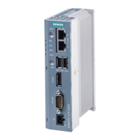
PN/M-Bus LINK
34 Operating Instructions, 03/2018, A5E44260928-AA
Connecting the M-Bus
Connecting the M-Bus
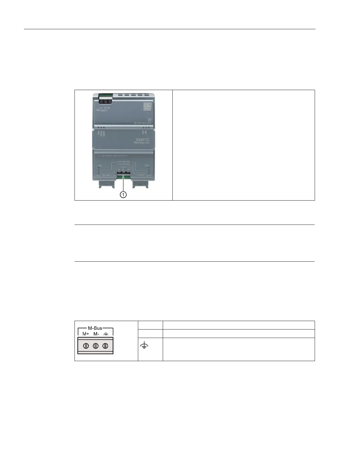
The PN/M-Bus LINK is connected to the M-Bus via a two-
wire cable to the M-Bus connection
①.
Conductor cross-section: max. 1.5 mm
2
Suitable cables: Twisted two-wire line YCYM or J-Y(ST)Y 2
x 2 x 0.8 mm.
To ensure interference-free communication, we recom-
mend that you use a shielded cable for the connection.
Note
The maximum permissible length of the connecting cable is 300 m.
Depending on the properties of the cable used, the baud rate and the number of connected
slaves, the permissible length of the cable can be less than 300
m.
The following figure shows the assignment of the terminal for the M-Bus connection.
Table 7- 2 Terminal assignment for the M-Bus connection
M-Bus cable shield
Also see information and notes on shielding in the section
Power supply and potential ratios (Page 28).
Permissible torques for screw terminal:
● Minimum tightening torque: 0.5 Nm
● Maximum tightening torque: 0.6 Nm
 Loading...