Functions
4.2 Response to errors
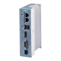
PN/M-Bus LINK
18 Operating Instructions, 03/2018, A5E44260928-AA
Response to errors
Diagnostic resource
The device provides various tools to isolate the cause. These tools are listed below:
LED display PN/M-Bus LINK signals its status with the LEDs on the front of the enclo-
sure. The meaning of the LEDs is described in section Status LEDs
SIMATIC diagnostics Information on the events that trigger a diagnostic message is available in
the section Events that trigger a diagnostic message (Page 45). This sec-
tion also includes a detailed description of the error that triggers the diag-
nostic message and possible measures.
See section Cyclic and acyclic data exchange (Page 15)
Device errors are indicated by the status LEDs. If necessary, corresponding diagnostic
messages are also issued. These can then be taken from the diagnostic buffer of the
S7 controller either immediately or during the next start-up.
Note
An Ethernet switch is integrated in PN/M
-Bus LINK. This switch is also operational in an
error state so that the PROFINET network continues to run.
 Loading...