Connecting
7.2 Power supply and potential ratios
PN/M-Bus LINK
28 Operating Instructions, 03/2018, A5E44260928-AA
Power supply and potential ratios
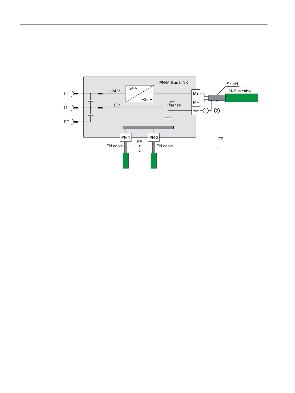
Block diagram
Alternative connection option for M-Bus cable shield:
Connection of the shield to M-Bus screw-type terminal
Connection of the shield to the shield busbar
Figure 7-1 Block diagram
Current consumption at the 24 V DC connection
The supply voltage for the M-Bus network is generated from the supply voltage at the
24 V DC connection by means of a DC/DC converter (boost converter). The generated
voltage is typically 12 V higher than the applied supply voltage. The current consumption at
the 24 V DC connection depends on the configuration of the M-Bus network.
Example 1: Typical current consumption
● Load on M-Bus: 5 standard loads (5 x 1.5 mA)
● Supply voltage: +24.0 V
● M-Bus voltage: +36 V
● M-Bus baud rate: 9600 Bd
● Communication at both PN ports
Total current = 85 mA (PN/M-Bus LINK) + 12 mA (M-Bus load current static) +
5 mA (M-Bus load current dynamic) = 102 mA
Taking into consideration a reserve (unit dispersion) of 8%, the total current is 110 mA.
 Loading...