Connecting
7.2 Power supply and potential ratios
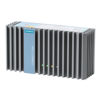
PN/M-Bus LINK
Operating Instructions, 03/2018, A5E44260928-AA
29
Example 2: Maximum current consumption
● Load on M-Bus: 40 standard loads (40 x 1.5 mA) + 1 x short circuit (100 mA)
● Supply voltage: +20.4 V
● M-Bus voltage: +32.4 V
● M-Bus baud rate: 9600 Bd
● Communication at both PN ports
Total current = 94 mA (PN/M-Bus LINK) + 276 mA (M-Bus load current static +
short-circuit current) + 6 mA (M-Bus load current dynamic) = 376 mA.
Taking into consideration a reserve (unit dispersion) of 6.4%, the total current is 400 mA.
The M-Bus connection provides the power supply of the M-Bus network and serves as
communication interface.
The master communicates with the slave through modulation of the voltage at the
M-Bus connection (mark state: 36 V typical, space state: 24 V typical).
The slave communicates with the master through modulation of the current consumption by
the slave (space state: +11…20 mA). The master hereby outputs the voltage for the mark
state (36 V typical) to the M-Bus network.
The required supply voltage for the mark state is generated by a DC/DC converter (boost
converter) from the voltage at the 24 V DC connection and is typically 12 V higher than this
voltage. The DC/DC converter is large enough that it can supply the current for the specified
number of M-Bus slaves, the current for communication and the current for the short-circuit
of a slave (max. 100 mA).
The current consumption by the M-Bus network is measured and evaluated by a
measurement resistance (R
Sense
) at the M-Bus negative terminal (-).
● The signals of the PROFINET interfaces are electrically isolated from each other, from
the internal electronics or 24 V supply voltage and from the fieldbus interfaces.
● The M-Bus interface is galvanically connected to the power supply.

 Loading...
